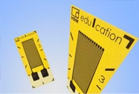
arrow_back_ios

Main Menu

See All Software See All Instruments See All Transducers See All Vibration Testing Equipment See All Electroacoustics See All Acoustic End-of-Line Test Systems See All Academy See All Resource Center See All Applications See All Industries See All Services See All Support See All Our Business See All Our History See All Global Presence
arrow_back_ios

Main Menu

See All Analysis & Simulation Software See All DAQ Software See All Drivers & API See All Utility See All Vibration Control See All High Precision and Calibration Systems See All DAQ Systems See All S&V Hand-held Devices See All Industrial Electronics See All Power Analyzer See All S&V Signal Conditioner See All Acoustic Transducers See All Current and Voltage Sensors See All Displacement Sensors See All Force Sensors See All Load Cells See All Multi Component Sensors See All Pressure Sensors See All Strain Sensors See All Strain Gauges See All Temperature Sensors See All Tilt Sensors See All Torque Sensors See All Vibration See All Accessories for Vibration Testing Equipment See All Vibration Controllers See All Measurement Exciters See All Modal Exciters See All Power Amplifiers See All LDS Shaker Systems See All Test Solutions See All Actuators See All Combustion Engines See All Durability See All eDrive See All Production Testing Sensors See All Transmission & Gearboxes See All Turbo Charger See All Training Courses See All Acoustics See All Asset & Process Monitoring See All Custom Sensors See All Durability & Fatigue See All Electric Power Testing See All NVH See All Reliability See All Vibration See All Weighing See All Automotive & Ground Transportation See All Calibration See All Installation, Maintenance & Repair See All Support Brüel & Kjær See All Release Notes See All Compliance
arrow_back_ios

Main Menu

See All nCode - Durability and Fatigue Analysis See All ReliaSoft - Reliability Analysis and Management See All API See All Experimental Testing See All Electroacoustics See All Noise Source Identification See All Environmental Noise See All Sound Power and Sound Pressure See All Noise Certification See All Industrial Process Control See All Structural Health Monitoring See All Electrical Devices Testing See All Electrical Systems Testing See All Grid Testing See All High-Voltage Testing See All Vibration Testing with Electrodynamic Shakers See All Structural Dynamics See All Machine Analysis and Diagnostics See All Dynamic Weighing See All Vehicle Electrification See All Calibration Services for Transducers See All Calibration Services for Handheld Instruments See All Calibration Services for Instruments & DAQ See All On-Site Calibration See All Resources See All Software License Management

Successfully compensating for lead resistances

Measuring points, e.g. at bridges or aircraft wings, are often located at greater distances from the measuring instruments. With measuring points that are not directly accessible, measuring instruments need to be connected using long cables. The disadvantage: The lead resistance in the cable can amount to several ohms and negatively affect the measurement. Particularly electrical resistance changes in the cable during measurement, e.g. due to temperature variations, have negative effects. With leads that are in series with the strain gauges (SG) in the same bridge arm, the temperature response due to heating of the cable is calculated as follows:  

 Q = Conductivity of the conductor material      

Example:

A copper lead of 1 m length (0.5 m each for feed and return lead) and 0.15 mm2 cross-section in series with a 120-ohm strain gauge causes 20 µm/m temperature response with 10 K temperature variation. All other conditions being equal, the temperature response with a 350-ohm strain gauge is only 7 µm/m. Various types of strain gauge circuits enable lead resistances to be compensated for. This article presents three types of circuits based on the Wheatstone bridge circuit explaining their advantages and disadvantages.

2-wire circuit

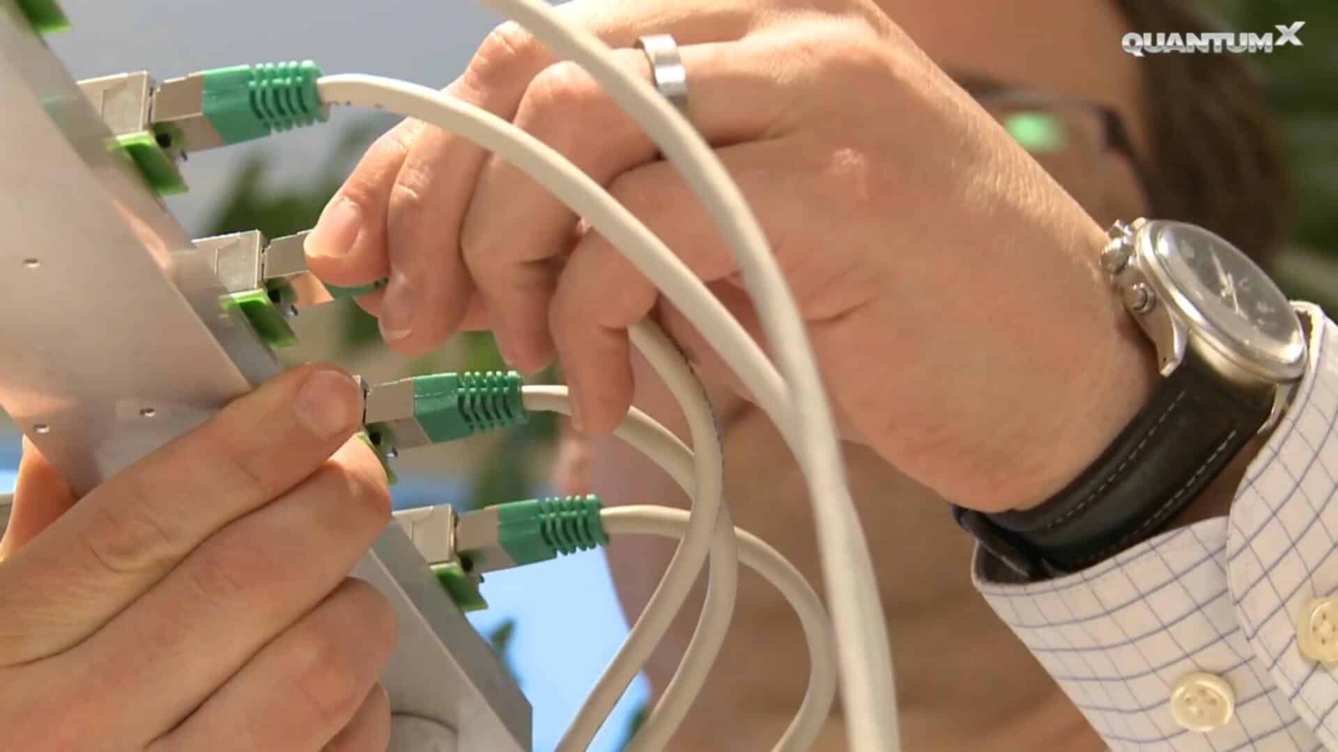
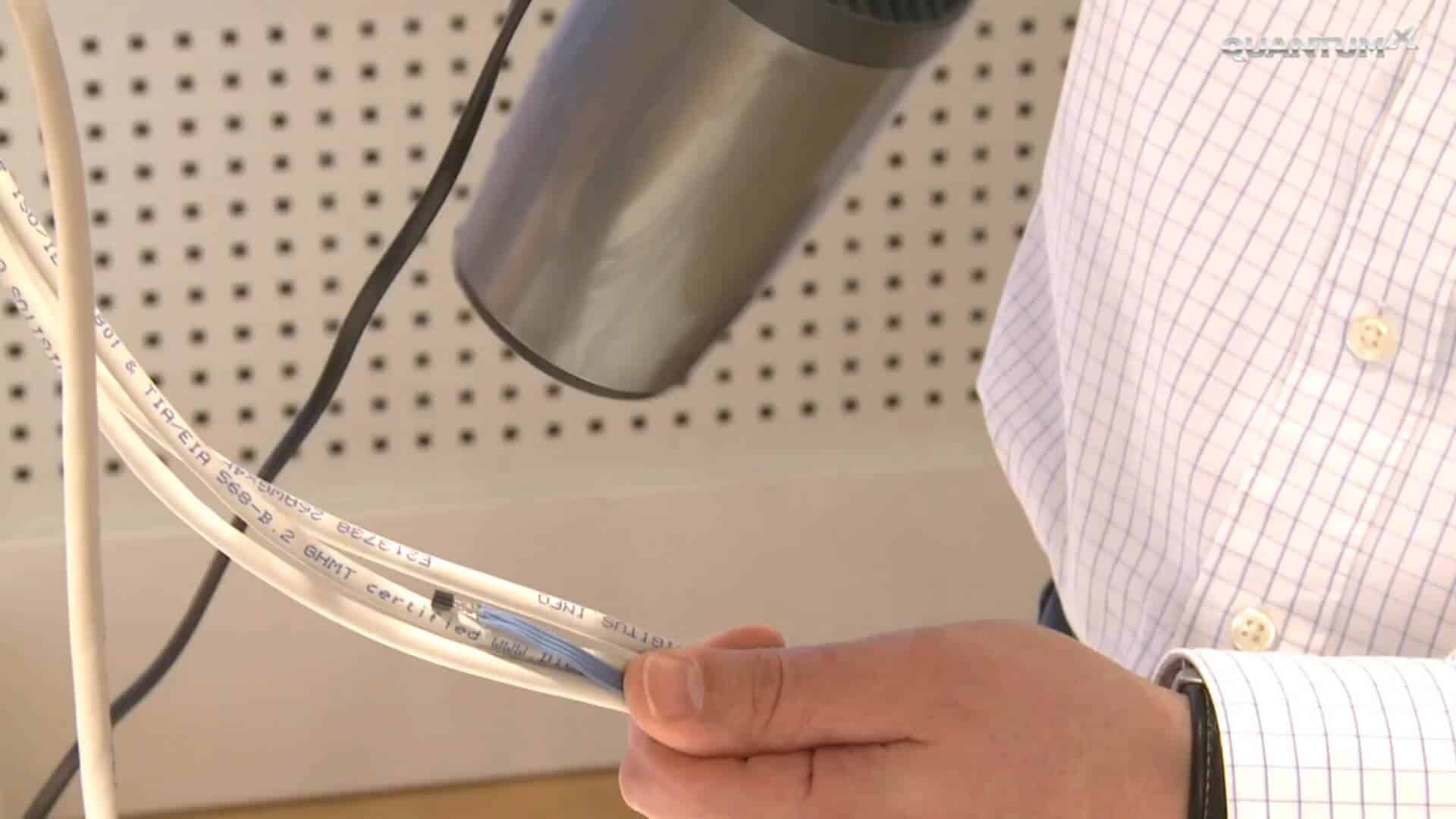
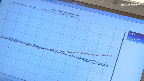
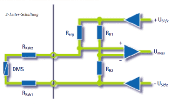
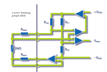
With the 2-wire circuit, the strain gauges and the amplifier are connected via two wires. The circuit diagram shows that the cable resistance is added twice (feed and return) to the strain gauge resistance.

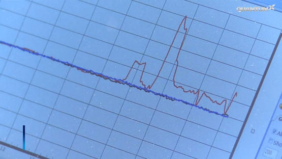
This affects both the bridge's zero point and its sensitivity. Even with cables with lengths of few centimeters it is essential to allow for the cable resistance. The 2-wire circuit is particularly sensitive to temperature variation during measurement, since the change in resistance immediately affects the measured value.

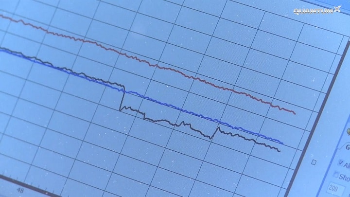
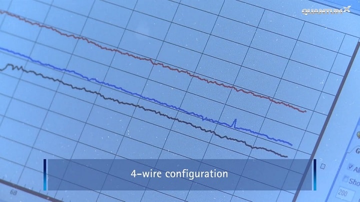
The 2-wire circuit's temperature stability has been tested using installed strain gauges and the QuantumX MX1615 strain gauge bridge amplifier. 

null
null
The test result: The measurement result obtained using a 2-wire circuit has no significance. The resistance change in the cable, e.g. due to temperature variation, fully impacts on the measurement result.
null
null
Asymmetric resistance changes to the strain gauge circuit too result in measurement errors. Changes in resistance are not corrected.null

Regulated 3-wire circuit

With the 3-wire circuit, an additional lead is connected to one connecting point of the measuring resistance, which results in a second measuring circuit that is used as a reference. The regulated 3-wire circuit measures the voltage across the upper cable resistance and increases the excitation voltage by double the amount measured. As a result the voltage across the strain gauge is identical with and without a cable and the cable has no influence on sensitivity. The regulated 3-wire circuit requires that the two current-carrying leads have identical resistance, since the voltage is measured only at one lead, however, double the value is applied for correction. Hence, with a cable with four leads, it would be completely wrong to connect two leads in parallel to reduce the cable resistance. This would result in a significant zero point error. On the other hand, with strain gauge rosettes and strain gauge chains, it is essential to make sure that resistor RKab1 corresponds to all RKab2 resistors connected in parallel.null
Our test too shows: Changes in resistance are corrected in one cable lead only. Asymmetric changes in resistance, e.g. interference at the points of contact, fully impact on the measurement result. Symmetric changes in resistance, e.g. temperature variation during the measurement, are compensated for by the sense lead.null

Regulated 4-wire circuit

Only the 4-wire circuit, or HBM's patented Kreuzer circuit, enables different cable resistances to be compensated for. A known electric current flows through the resistor via two of the leads. The voltage drop at resistor RKab1 is corrected (at high impedance) via two additional leads. The Kreuzer circuit measures the voltage across resistor RKab2 and adds it to the excitation. The voltage and thus the current through completion resistor Rerg are independent of the cable resistance. Zero point and sensitivity errors resulting from cable effects are electronically compensated for.null
Note: the three graphs show a stain gauge measurement using 2-, 3- and 4-wire circuits. Here it seems that all three techniques offer identical stability. Ideally, we see steps in the graphs for 2- and 3-wire; with 4-wire, the graph remains stable. Our test proves: The patented Kreuzer circuit allows for precise measurement results through
  • high temperature stability
  • and correction of changes in resistance in both cable leads.
Asymmetric changes in resistance, e.g. at connectors, and symmetric changes in resistance, e.g. through temperature variation, are corrected and do not affect the measurement result. 


null

Strain gauges from HBM

Go to the strain gauge overview

Recommended for you