A specific problem addresses the ultimate topic: how to turn part of a structure into a sensor (Figure 4). In this example, a customer has a motor that is going to drive a ball screw through a press to do some work within the chamber shown above. What is needed is to determine the actual force value because there is a range the customer requires to be in a control circuit to drive this motor. The product is being loaded into the upper area and after reviewing this, it was determined to turn this press member into an active sensor as it would cause no changes to the system structure.
How to Turn a Component into an Active Sensor
In many applications requiring force, load, pressure, or torque measurements, you may not have the ability to install a standard off-the-shelf sensor due to space considerations or costly modifications to your existing structure. This white paper provides an overview of the most effective way to use a strain gage to turn an existing load-carrying part or support into a sensor.
Types of Strain Gages
There are different categories of strain gages to help meet many applications. A single linear strain gage is what we call a quarter bridge that can be used in a number of different ways. The T-rosette type has two measuring grids or what we call a ½ bridge were each grid is arranged at a 90° offset from each other, enabling measurement of axial strain and Poisson’s effect on the same strain gage backing. This technique can be used in bending/shear beams, column types or for measuring torque.
Applications
There are many applications for strain gages. Depending on the measurements to be taken different strain gage patterns can be used. Some application examples are shown in Figure 1. In medical applications, strain gages are used to sense occlusion in infusion pumps as pressure, torque in medical robots, and force in all types of medical devices that may require the gages or sensors to survive hundreds of autoclave cycles.
As farm equipment has become “smarter,” strain gage sensors are used in all types of applications such as downforce sensors for seeding machines and torque for autonomous tractors. For cranes and off-highway vehicles, there are many safety aspects that need to be accounted for as far as overturn or over lift protection. Today’s industrial robots are moving into all fields of manufacturing and require sensors for precise force feedback loops. It all comes back to different sensors that can measure the mechanical changes and how you adapt a sensor for the most accurate measurement.
Figure 1: Applications





Principles
Force, mass, torque, and pressure are the four basic principles of measurement. If you think of a support column, a force is applied via tension or compression. What ultimately happens is that the beam is expanding when pulling on the beam and contracting when a compressive load is pushing down and the beam gets wider.
In this example, axial strain is positive when pulling on the beam; compressive strain on a 90º Poisson gage is negative in compression because the beam is going to get thinner. The opposite happens on a column type of cell when you are pushing on the beam. The basic strain equation is Δl over original l and this is what applies to all these types of measurements.
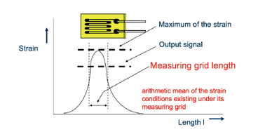
When you place a strain gage on these supports, it is not on a single active point that you’re measuring. There is an arithmetic mean across the active grid length, which is in between the turnaround points of the actual strain gage grids. With the point described in Figure 2, you’ll get an average of all of the strains across the entire measuring grid length. And that is what will give the average output for this example.
When thinking about where to place the gage on a support, you must consider the maximum strength of the support so the load does not go beyond the strain limits of the gage. In addition, have as flat of an average strain area as possible to maintain the level of accuracy.
Configurations
When turning a component into an active sensor, there are basic configurations. In a bending beam configuration, there is a structural beam with a force being applied — it could be as simple as a cantilever-type beam approach. With cantilever beams, there are positive strains on the top surface and negative on the bottom. This is the basic principle of a cantilever. In this example, there are two active tension gauges on the top surface and two active compressor gages on the bottom. These are wired up into a Wheatstone bridge circuit configuration, which will provide the output of an applied force. You do need to consider moment influences or in other words if a force moves in or out or it is not a point load, there could be a varying impact because nothing is being done in this example to cancel out for moment load influences.
Another example is a column configuration. This is used when dealing with either force or tension on a column or beam. This gage pattern is set up to measure axial and Poisson’s effect below. Another set of these gages would be on the opposite side wired together to make a full Wheatstone bridge. In this equation, stress is equivalent to the force over the cross-sectional area where the gages are located. To measure torque within a part, a rod, or other type of pole you have two opposing moments and twisting is occurring in the beam. That twisting can be measured along the central axis with a set of shear gages that will measure the 45-degree strains created by the torque. This can be wired together to create a full Wheatstone bridge and provides the basic approach to measuring torque.
The last principle is a shear beam configuration that is similar to our earlier cantilever type beam; in this case, the advantage is in using a shear principal vs a bending beam approach. By using the shear principle of measuring the strain with the force applied, gages are deposited along the neutral axis of the beam, making this configuration moment insensitive. Force can be moved in and out without adverse effects of that change in load on the output.
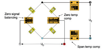
When wiring up a Wheatstone bridge, the basic configuration can be illustrated in terms of a baseball diamond (Figure 3). Between home plate and first base is the first active gage. The two polarities are always configured to be opposite each other — either two tensions opposite each other or two compressions opposite each other. This is what is going to create the unbalance in the bridge when the load is applied — this is the signal that actually will be measured. Shown in Figure 3 is span temperature compensation, which is when you attempt to compensate the Wheatstone bridge for the temperature effect of Young’s modulus of the base material. Material selection can be very important. A structural member of a frame may be made of wrought iron or another material that is not intended to be a sensor because it does not have springlike qualities — alloy steels, stainless steels, or aluminum would be sensor-grade materials. Then you can set up compensation to offset the effects of Young’s modulus. When a voltage is applied, as Young’s modulus is changing on the material (which is going to change the strain), these parts will do the opposite and actually shunt the voltage or allow more voltage into the bridge to mask the effect of temperature from the base material.
The other aspect is zero temperature compensation internal to the bridge. Here, we are concerned with the actual temperature effect of the actual bridge circuit; within it, there could be a different material that will offset for that change. The net effect is that there will be no change in signal with change in temperature. On the opposite arm is a zero-signal balancing network. The network is made out of the same material as the strain gages, which is a constantan alloy. The zero correction network is utilized because once the gages are placed down and internal wires are connected there could be a raw zero unbalance. These networks don’t take up extra signal from the amplifier circuit but provide a method to adjust the zero signal of the bridge circuit. Zeroing the bridge helps to allow the maximum resolution from the amplifier being used.
Turning Part of a Structure into a Sensor
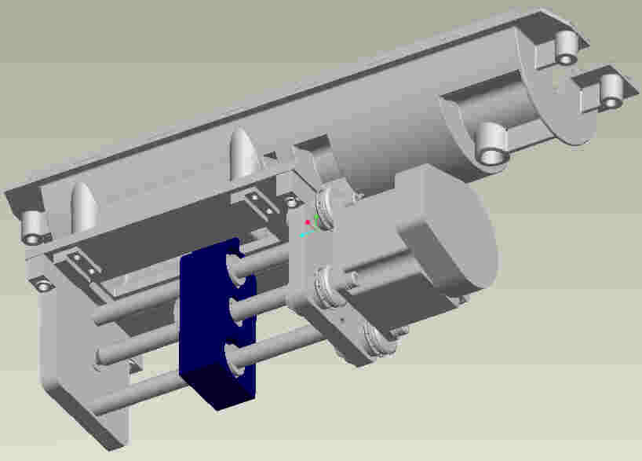
The customer wants as accurate a load measurement as possible with temperature compensation to avoid issues of varying temperatures on the measuring signal . They are unable to control how the load is going to be applied — whether it is always going to be in line; therefore, has to be insensitive to moments. In this case, there is no place to put a catalog sensor because of the space limitations.
What is not being shown is what’s happening above in the upper chamber. There is a very small space that sticks through the chamber; there is no place to add a catalog force-type sensor in this application. The blue member was identified as the possible solution. We started taking the known loads that the customer had provided as far as what is going to be applied to the beam. Then we determined how to strategically weaken this so that we promote deflections — strain that we can measure.
We weakened the part by putting a through hole which allowed us to, with the applied load, develop the necessary deflections. In Figure 5, the colors indicate that the negative and positive strains are internal to the hole so that with linear gages, a full Wheatstone bridge circuit can be created within this hole. The configuration will work best in this case and allow us to meet the customers accuracy requirements. There is also plenty of space within this hole for the temperature compensation circuit.
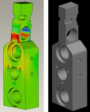
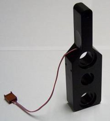
The existing part is made of a very basic structural material. It was not set up to be sensor-grade or what would normally be used for a sensor. The material was changed to provide the spring-like characteristics that were needed. As far as the finite element analysis (FEA), several iterations were run to determine the best hole sizes in order to turn this into a workable active sensor.
Figure 6 shows the finished part which consists of aluminum material which ultimately was used with an anodized solution for protection. A full bridge millivolt/volt output sensor was designed to fit into the space and the whole sensor is moment insensitive and had natural cancellation designed in. The part is capable of carrying 150% of the original capacity without having zero shifting or zero movement. The part was then run through a prototype process to simulate the actual load conditions and perform 100% testing and calibration.
Summary
When this customer came to us, they were hoping to find a catalog product that could simply drop into this part with very little to no modifications. This was not possible and through our work we could utilize an existing structural member of the customers system and turn this into the actual active sensor. This sensor then gave the desired electrical signal for applied load needed and no changes were needed in the customers system.
Author
Randy Hopkins
Director of OEM Sensors at HBK
Related Pages

Contact Our OEM Sensor Team
Contact our experienced team of design engineers for more information and to discuss your project needs.
