Setting up the measurement interface in Perception
First adjust the resolution under Settings ➔ General ➔ Recorder. 16 bits is selected by de-fault. This needs to be changed to 18 bits to analyze the angle of rotation so that the Timer-Counter Channels can be activated later.
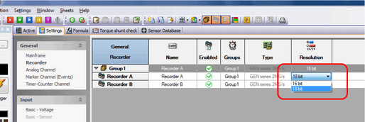
Figure 1: Changing the recorder setting to 18 bits
The optical signal converter between the incremental rotary encoder and the GEN3i (see Annex A) is hardwired to the Marker Channels (Events)
Ev A7_01 (encoder track K0)
Ev A7_02 (encoder track K1)
Ev A7_03 (encoder track K2)
on input card A. (See the GEN3i data sheet page 8, Figure 1.6: Pin diagram for Digital Event/Timer/Counter connector)
These channels will now be activated in Perception (Settings ➔ General ➔ Marker Channel (Events)):
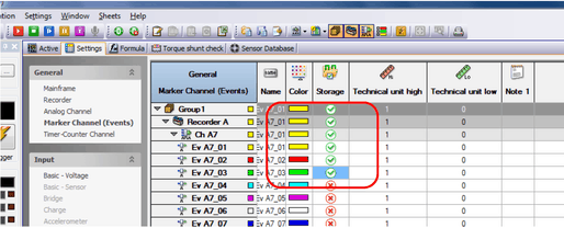
Figure 2: Activating the digital inputs
Now activate the appropriate Timer-Counter Channel (Ch A9) under the General menu item to analyze the position:
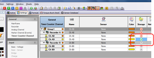
Figure 3: Activating the Timer-Counter Channel
If it has not been done already, create a suitable sensor in the sensor database (Sensor Database worksheet). Initially no direction will be analyzed (select Counter Type: Uni Directional). To reset the counter after 1024 pulses, select option Reset counter each external pulse. Make the other settings shown in the figure below as well:
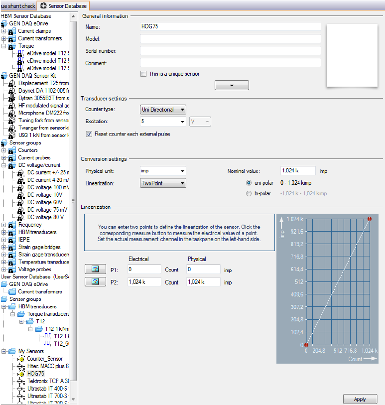
Figure 4: Creating an incremental rotary encoder in the sensor database
Then you can select the sensor for Timer-Counter input CH A9 under Settings ➔ Input ➔ Timer Counter. The corresponding settings appear on the right:
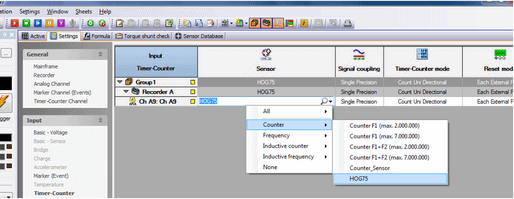
Figure 5: Selecting the sensor you created
Reset the Invert reset pin option:
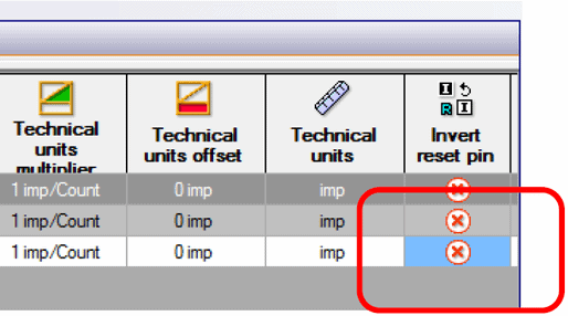
Figure 6: Resetting inversion of the signal
Now you can drag the counter into the Active page and use it as you normally do:
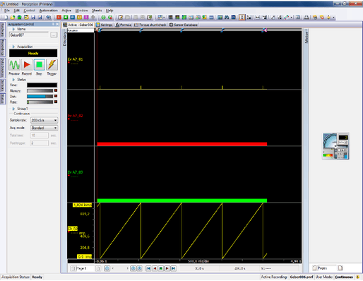
Figure 7: Display of the encoder signal in Perception


