惠斯通电桥可以用各种方式测量电阻:
- 通过与已知电阻比较来确定电阻绝对值
- 测定电阻的相对变化
后一种方法用于应变技术。它可以测定应变片电阻的相对变化,通常精度可达 10-4 到 10-2 Ω/Ω。
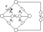
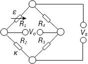
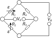
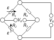
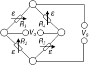
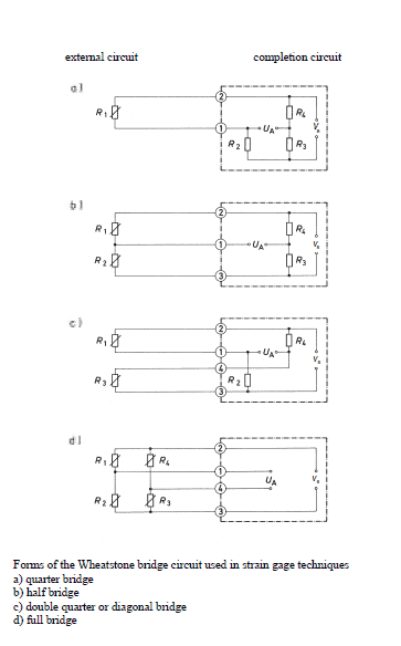
下面的图片显示了惠斯通电桥的两个不同的电气连接图,它们是完全相同的:图a)显示了通常使用惠斯登电桥的菱形连接;和图b)是相同电路,这对于未经过电气训练的人来说,这将更清楚。
惠斯通电桥可以用各种方式测量电阻:
后一种方法用于应变技术。它可以测定应变片电阻的相对变化,通常精度可达 10-4 到 10-2 Ω/Ω。
下面的图片显示了惠斯通电桥的两个不同的电气连接图,它们是完全相同的:图a)显示了通常使用惠斯登电桥的菱形连接;和图b)是相同电路,这对于未经过电气训练的人来说,这将更清楚。
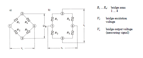
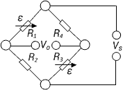
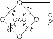
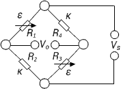
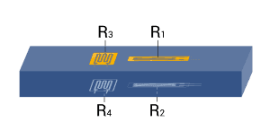
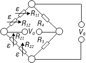
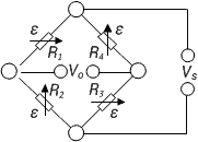
惠斯通电桥的四个桥臂或分支由电阻R1至R4组成。桥的角点2和3指示桥路激励电压Vs的连接;角点1和4为电桥输出电压V0即测量信号。
注意: 对桥路组件和连接没有普遍接受的规则。 在现有的文献中,有各种各样的名称,这反映在桥路方程中。 因此,为了避免误解,必须考虑方程中使用的名称以及它们在桥路中的位置。
如果供电电压 Vs 被施加到电桥终点2和3,那么供电电压被 R1, R2 和 R4, R3 分成两个半桥,即每个半桥形成一个分压器。
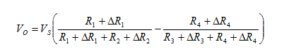
由于 R1, R2 和 R3, R4. 的电阻电压不同,电桥可能不平衡。 计算如下:
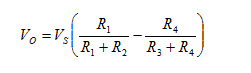
如果桥路平衡,并且
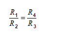
则电桥输出电压 V0 为零。
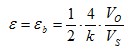
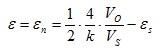
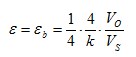
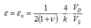
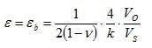
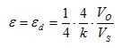
在预设应变的情况下,应变计的电阻变化量 ΔR. 我们给出了以下等式:
对于应变测量,电阻 R1 和 R2 在惠斯登电桥中必须相等。
这同样适用于 R3 和 R4.
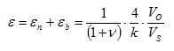
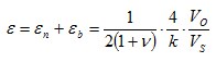
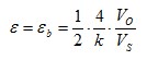
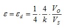
通过一些假设和简化,可以确定以下等式(在HBM的书“使用应变片进行测量的介绍”中给出了进一步的解释):
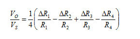
在计算的最后一步中, ΔR/R 必须由以下代替:
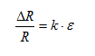
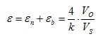
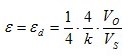
这里k是应变片的k系数,, ε 是应变。
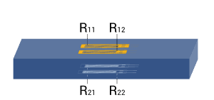
方程式假设桥臂中的所有电阻都改变了。 例如,这种情况发生在传感器或被测对象执行类似的功能。 在实验应力测试中,这种情况几乎不存在,因为通常只有一部分桥臂采用应变片,其余部分由桥接电阻组成。 一般称为四分之一桥,半桥,双四分之一或斜桥和全桥。
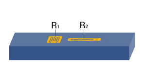
根据不同测量任务,测量点上会使用一个或多个应变片。例如全桥、半桥或四分之一桥等表示,实际上它们是不正确的。事实上,测量电路总是完整的,由应变片和含有应变片的试样以及固定电阻来组成 ;
传感器通常要比实验应力测试有更严格的精度要求。一般来说,传感器在所有四个桥臂上都采用应变片(全桥电路)。
如果需要消除各种干扰,应采用全桥或半桥电路进行应力分析。非常重要的是,不同应力状况是有明显区别的,例如压向或拉向,以及弯曲、剪切或扭转应力等。
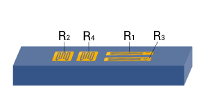
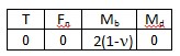
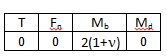
下表显示了应变片的几何位置、桥路的类型和桥路系数 B 对额定力、弯矩、扭矩和温度的依赖性。每个例子的小表描述的是每种影响量指定的桥路系数 B。该方程用于计算路输出信号 VO/VS 的有效应变。
Bridge configuration | External impacts measured: | Application | Description | Advantages and disadvantages | ||
| 1 |
|
|
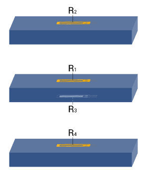
| Strain measurement on a tension/ compression bar Strain measurement on a bending beam | Simple quarter bridge Simple quarter bridge circuit with one active strain gauge | + Easy installation - Normal and bending strain are superimposed - Temperature effects not automatically compensated |
| 2 | |
|
| Strain measurement on a tension/ compression bar Strain measurement on a bending beam | Quarter bridge with an external dummy strain gauge Two quarter bridge circuits, one actively measures strain, the other is mounted on a passive component made of the same material, which is not strained | + Temperature effects are well compensated - Normal and bending strain cannot be separated (superimposed bending) |
| 3 |
|
|
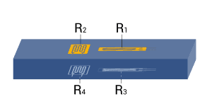
| Strain measurement on a tension/ compression bar Strain measurement on a bending beam | Poisson half-bridge Two active strain gauges connected as a half bridge, one of them positioned at 90° to the other | + Temperature effects are well compensated when material is isotrop |
| 4 |
|
|
| Strain measurement on a bending beam | Half bridge Two strain gauges are installed on opposite sides of the structure | + Temperature effects are well compensated + Separation of normal and bending strain (only the bending effect is measured) |
| 5 |
|
|
| Strain measurement on a tension/ compression bar | Diagonal bridge Two strain gauges are installed on opposite sides of the structure | + Normal strain is measured independently of bending strain (bending is excluded) |
| 6 |
|
|
| Strain measurement on a tension/ compression bar Strain measurement on a bending beam | Full bridge 4 strain gauges are installed on one side of the structure as a full bridge | + Temperature effects are well compensated + High output signal and excellent common mode rejection (CMR) - Normal and bending strain cannot be separated (superimposed bending) |
| 7 | |
|
| Strain measurement on a tension/ compression bar | Diagonal bridge with dummy gauges Two active strain gauges, two passive strain gauges | + Normal strain is measured independently of bending strain (bending is excluded) + Temperature effects are well compensated |
| 8 |
|
|
| Strain measurement on a bending beam | Full bridge Four active strain gauges are connected as a full bridge | + Separation of normal and bending strain (only the bending effect is measured) + High output signal and excellent common mode rejection (CMR) +Temperature effects are well compensated |
| 9 |
|
|
| Strain measurement on a tension/ compression bar | Full bridge Four active strain gauges, two of them rotated by 90° | + Normal strain is measured independently of bending strain (bending is excluded) + Temperature effects are well compensated + High output signal and excellent common mode rejection (CMR) |
| 10 |
|
|
| Strain measurement on a bending beam | Full bridge Four active strain gauges, two of them rotated by 90° | + Separation of normal and bending strain (only the bending effect is measured) + Excellent common mode rejection (CMR) + Temperature effects are well compensated |
| 11 |
|
|
| Strain measurement on a bending beam | Full bridge Four active strain gauges, two of them rotated by 90° | + Separation of normal and bending strain (only the bending effect is measured) + High output signal and excellent common mode rejection (CMR) + Temperature effects are well compensated |
| 12 |
|
|
| Strain measurement on a bending beam | Half bridge Four active strain gauges connected as a half bridge | + Separation of normal and bending strain (only the bending effect is measured) + Temperature effects are well compensated + High output signal and excellent common mode rejection (CMR) |
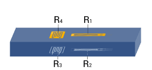
| 13 | 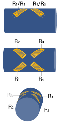 |
|
| Measurement of torsion strain | Full bridge Four strain gauges are installed, each at an angle of 45° to the main axis as shown | + High output signal and excellent common mode rejection (CMR) + Temperature effects are well compensated |
| 14 | 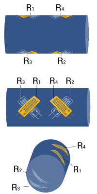 |
|
| Measurement of torsion strain with limited space for installation | Full bridge Four strain gauges are installed as a full bridge, at an angle of 45° and superimposed (stacked rosettes) | + High output signal and excellent common mode rejection (CMR) + Temperature effects are well compensated |
| 15 | 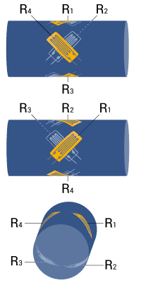 |
|
| Measurement of torsion strain with limited space for installation | Full bridge Four strain gauges are installed as a full bridge at an angle of 45° and superimposed (stacked rosettes) | + High output signal and excellent common mode rejection (CMR) + Temperature effects are well compensated |
注意: 假设圆柱轴用于扭矩测量,如13, 14和15。由于对称性的原因,允许在 x 和 y方向弯曲。同样也适用于矩形或矩形截面的杆件。
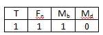
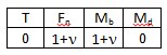
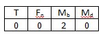
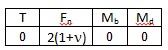
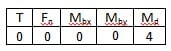
符号解释:
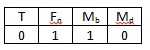
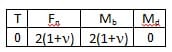
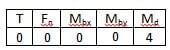
| T | 温度 |
| Fn | 径向, 额定力 |
| Mb | 弯矩 |
| Mbx, Mby | X 和 Y 方向弯矩 |
| Md | 扭矩 |
| εs | 表观应变 |
| εn | 径向,额定应变 |
| εb | 弯曲应变 |
| εd | 扭矩应变 |
| ε | 测量点有效应变 |
| ν | 泊松比 |
| 有源应变片 | |
| 带温度补偿的应变片 | |
| 电阻或应变片 |
| 主题/描述 | 语言 | 产品 | 语言 | 内容类型 |
|---|---|---|---|---|
| Tech Notes | ||||
| Anwendung der Wheatstone'schen Brückenschaltung - Technische Information | German | |||
| Applying the Wheatstone Bridge Circuit - Technical Information | English | |||