HBM 还提供可焊接 electrical and 光纤应变片和传感器。
The Impact of Spot Welded Strain Gauges to Steel Material
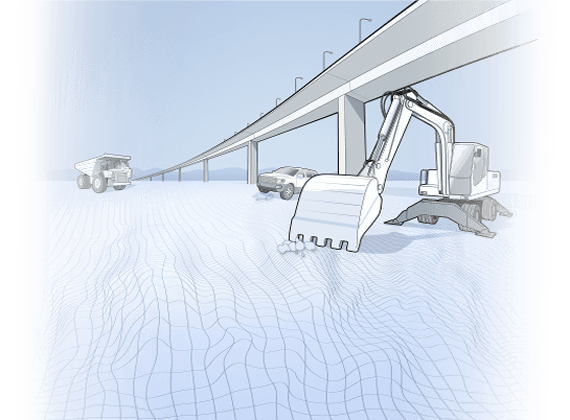
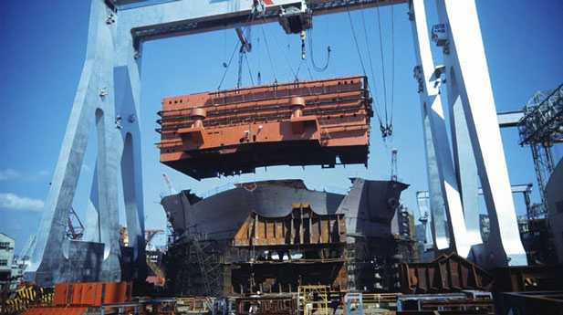
Engineers measure strain on strongly impacted areas of their structure, such as crane bars, insertion spots for bridge cables, and other construction elements in ruggedized environments. These areas are designated for notch effects with respect to mechanical stress and could lead to failure. The environment for these applications is rough, which makes it difficult for application of strain gauges applied by adhesive. However, with the welded strain gauges from HBM, it is feasible to test your construction with respect to stress and strain.
Welding procedures commonly known from industry, such as metal inert gas welding (MIG), metal active gas welding (MAG), tungsten inert gas welding (TIG), are immensely rough procedures which influence the base material strongly. Here the surface of the elements to be connected is molten.
The resistance spot welding used for strain gauges impacts the structure only in a minor way.
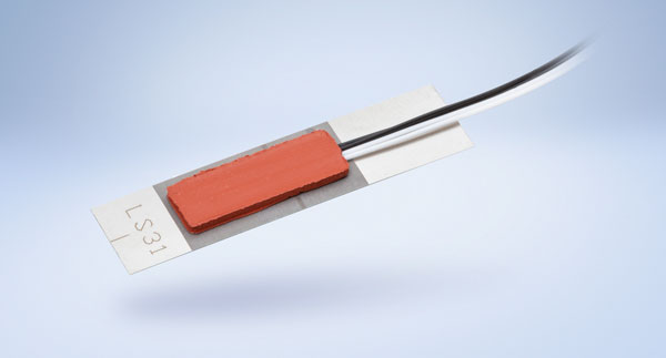
This article analyzes the influence of the weldable electrical strain gauge LS31 to the base material. These results are also valid for the HBM FiberSensing optical weldable sensors. Several tests have been performed, which show that the impact to the base material is very limited.
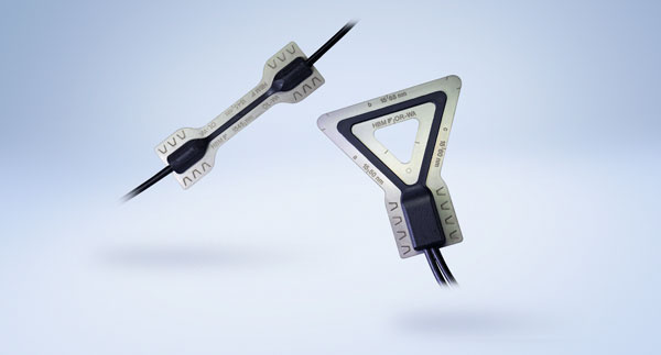
HBM 可焊接应变片
点焊基础材料试验
以下测试是由“Schweitechnische Lehr-und Versuchsanstalt Mecklenburg-Vorpommern GmbH” 进行的。其证明了应变片点焊对基础材料的微小影响 [1]。
测试说明
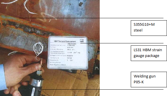
HBM 应变片被焊接到 S355G10+M 钢材上 (400 x 200mm, t=80mm)。其采用 Heller C39 型移动式接触焊枪 P05-K 进行焊接,安装的是 HBM LS31 应变片。焊接前,将表面磨光使金属表面完全裸露。
随后按照 DIN EN ISO 15613 标准进行不同的测试:
- 目视检查剥离试验
- 显微镜检查
- 硬度试验
焊接和基础材料检查
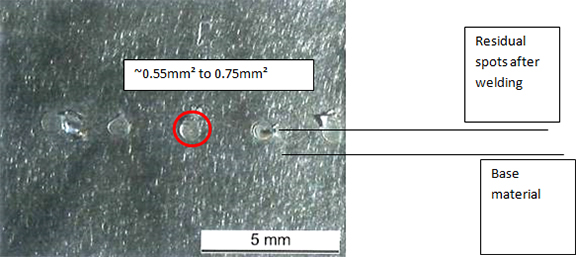
1. 目视检查和剥离试验(DIN EN ISO 17637)
根据 DIN EN ISO 17637 标准剥离试验进行的目视检查显示没有明显缺陷。基材的表面在焊接镜片中没有裂纹。
对基材的影响仅限于焊点。

目视检查后,进行剥离试验。应变计基底剥离后,没有任何基材被剥离。并且焊点可被磨掉。
2. 显微镜检查(显微照片 DIN ISO ISO 17639)
然后是检查焊点的横截面。剥离试验后对材料进行刻蚀,制成光学显微照片。材料则通过显微镜检查(DIN EN ISO 17639)。
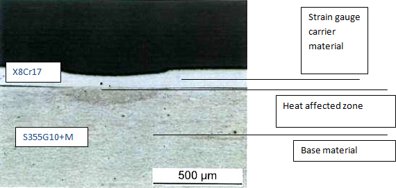
焊接的横截面约为 0.5-0.8 mm²,深度约为0.05mm,这对基体材料影响很小。热影响区清晰可见:
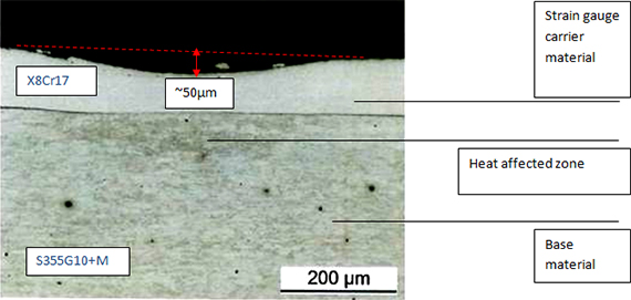
横截面显示相同的结果。热影响区仅限于焊点区。
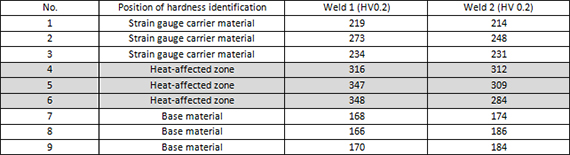
3. 硬度试验(DIN EN ISO 9015-2)
根据 Vickers 程序进行硬度试验,在横截面上的不同位置进行。
1-3: 在应变片基底材料(X8Cr17)
4-6: 钢材的热影响区
7-9: 钢材料

该值表明在热影响区的硬度增加。没有达到标准(350HV 0.2)的最大极限,这意味着测试标准得到满足。
总结
- 应变片点焊融化影响通常深度小于 100µm,横截面小于 1mm² 。 SLV [1] 试验结果证实了这一点。
- 焊点在应变片基底和钢体和基材之间形成坚固连接,从而能够进行应变传递。
- 点焊后,钢体材料或应变片中无裂纹。
参考文献
Schweißtechnische Lehr- und Versuchsanstalt Mecklenburg-Vorpommern GmbH 公司报告。
[1] 报告 - 编号: PB210-170421-01E REV0 ()按照 Din EN ISO 15613 标准进行在点焊接的评定试验)
法律免责声明:技术提示目的在于提供一个快速的概述。并且会不断完善。HBM对描述的正确性和/或完整性不承担任何责任。我们保留在任何时间更改和/或说明的权利,恕不另行通知。