Aug 29 2019
Setting up a Force Measurement Chain in Test&Measurement
Read More
Did you ever ask yourself what happens to your sensor when you order a calibration in accordance with ISO 376 and what the values on the calibration certificate refer to? If so, you can find a short summary of the most accepted standard in the world of (reference) force measurement in this white paper.
Calibration in general describes the comparison of the measurement results of a sensor under test with a calibration standard. This means that a calibration always results in knowing the output signal of a force transducer when loaded with a certain force along with the uncertainty of the load cell at this force step.
In the case of force transducers, there are two methods of calibration:
Calibration ensures that a load cell works properly, and it also uncovers the characteristics of the individual force transducer. You can, therefore, trust the measurement results measured with a calibrated sensor. Additionally, calibration helps with a better measurement uncertainty calculation as the characteristics on the calibration certificate for the particular load cell are in most cases much more precise than the specifics given in the datasheet and that apply to the whole model series.
In the world of reference force transducers (force transfer standards), DIN EN ISO 376 is the globally accepted standard. It applies to master sensors as well as many industrial applications. While it is more complex than a working standard or DKD-R 3-3 calibration, it is also much more accurate and often required.
The summary given here cannot substitute for the complete ISO 376 standard, but it will help you understand what happens if you send your force transducer to the HBK calibration laboratory for an ISO 376 calibration.
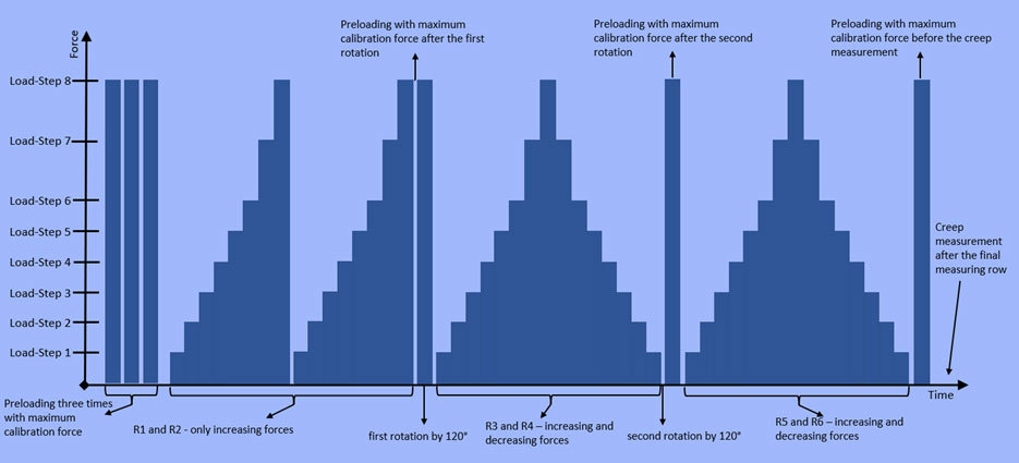
Every ISO 376 calibration begins with preloading the sensor three times. Each time, the pre-load is applied with the maximum calibration force.
In the next phase of the testing procedure, the sensor is loaded up to the maximum calibration force with increasing loads in eight to ten steps. After unloading, the same procedure is repeated in an unchanged mounting position. In other words, the load cell remains unmoved within the calibration machine and the same load steps are repeated a second time.
When this has been completed, the sensor is dismounted, rotated by 120° and reinstalled in the calibration machine. Following a preloading with the maximum calibration force, the load steps from the previous phase are applied to the sensor again up to the maximum calibration force and then unloaded at the same intervals. Note that the load step used when decreasing the force are the same as during the increase. This differs from the previous two phases of the testing procedure, where the sensor was unloaded from the maximum calibration force to zero at once.
After dismounting the sensor for a second time, it is again rotated by 120° and fully preloaded to its maximum calibration force. Then, it is uploaded and unloaded another time with the same load steps as described above for the previous part of the test.
After the sensor is unloaded again, the last step of the procedure is a creep measurement.
After the sensor is unloaded again, the last step of the procedure is a creep measurement.
After the sensor is unloaded again, the last step of the procedure is a creep measurement.
All calibration certificates show the results for every measurement row (R1 – R6) in detail:
→ ROTATION BY 120°
→ ROTATING BY 120°
→ Creep measurement
To be able to compare the different force sensors and assign them to an appropriate accuracy class, the characteristic values must be determined and evaluated for each sensor and every load step. The following specifications are calculated from the testing procedure described above:
Repeatability: The difference in output signal in unchanged mounting position
Reproducibility: Describes the difference in output signal at the same load step in different mounting positions
Interpolation error: The interpolation error shows the difference between the real characteristic curve of the sensor and the curve fitting
Reversibility/Hysteresis: Describes the difference in output signal between increasing and decreasing load cycle at a certain load step
Creep error: Indicates the change of output signal under constant load
Zero error: Indicates the deviation of the zero point before and after a loading/unloading circle.
Except for the zero error, all characteristics are calculated relative to each individual load step, meaning relative to the actual value. It is a fact that the result of a calibration can never be more precise than the calibration machine used. Therefore, the uncertainty of the calibration machine is an important point to be considered.
Expanded uncertainty of applied force: This error doesn’t relate to the load cell, but to the used calibration machine
View the HBK force measurement glossary for more information on the characteristics described here.
Every transducer calibrated according to DIN EN ISO 376 receives a calibration certificate that evaluates the characteristic values of the sensor and provides information about the calibration machine used, their traceability and uncertainty and the environmental conditions during the calibration procedure. On the certificate you can find the uncertainty for the calibrated load cell for every load step for four different use cases:
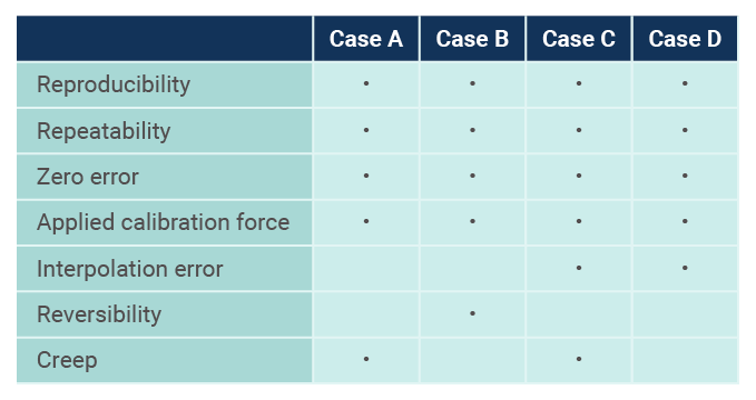
Case A: Only for increasing forces when using the sensor only for forces equal to a load step of the calibration
Case C: Only for increasing forces, but can be used for any force in the calibration range
Case B: For increasing and decreasing forces the use of the sensor is only for forces equal to the load step of the calibration
Case D: For increasing and decreasing forces, but can be used for any force in the calibration range
The four cases include different characteristic values in the calculation of the measurement uncertainty. For example, case A doesn’t take the interpolation error and the reversibility into account, but case D does.
The uncertainty is given as an ‘expanded uncertainty’, which means it is given for coverage factor k=2. That means that 95% of all tests will be in this range of uncertainty.
A complete breakdown of which case considers which measurement errors can be found below.
Additionally, you will find a classification for every load step and every case, with 00 being the best class and 2 being the worst. As the force transducer receives a classification for each load step, the classes can be specified in ranges. For example, a sensor fulfils the requirements of class 00 from 40% to 100% of the nominal force, but only class 0.5 from 10% to 29,99999%.
HBK guarantees the accuracy class of the sensors if ordered along with a calibration. You can find the measurement ranges and the accuracy class in accordance with ISO 376 in the table below.
| Sensor | Class | Measurement Range |
|---|---|---|
| C15 | 00 | 10% – 100% |
| U15 | 0.5 | 10% – 100% |
| Z4A | 00 | 20% – 100% |
| Z30a | 00 | 20% – 100% |
| C18 | 0.5 | 20% – 100% |
| C5 | 00 | 40% – 100% (20% - 100%) |
Figure 4 – HBK sensors and their measurement ranges
At HBK, the accuracy class in accordance with ISO 376 is always defined with a measurement range counting for all use cases.
For higher demands on sensor accuracy, the HBK top transfer force sensors have even better technical characteristics than the ones required by class 00 ISO 376.

This will bring together HBM, Brüel & Kjær, nCode, ReliaSoft, and Discom brands, helping you innovate faster for a cleaner, healthier, and more productive world.
This will bring together HBM, Brüel & Kjær, nCode, ReliaSoft, and Discom brands, helping you innovate faster for a cleaner, healthier, and more productive world.
This will bring together HBM, Brüel & Kjær, nCode, ReliaSoft, and Discom brands, helping you innovate faster for a cleaner, healthier, and more productive world.
This will bring together HBM, Brüel & Kjær, nCode, ReliaSoft, and Discom brands, helping you innovate faster for a cleaner, healthier, and more productive world.
This will bring together HBM, Brüel & Kjær, nCode, ReliaSoft, and Discom brands, helping you innovate faster for a cleaner, healthier, and more productive world.