arrow_back_ios

Main Menu

See All Software See All Instruments See All Transducers See All Vibration Testing Equipment See All Electroacoustics See All Acoustic End-of-Line Test Systems See All Academy See All Resource Center See All Applications See All Industries See All Services See All Support See All Our Business See All Our History See All Global Presence
arrow_back_ios

Main Menu

See All Analysis & Simulation Software See All DAQ Software See All Drivers & API See All Utility See All Vibration Control See All High Precision and Calibration Systems See All DAQ Systems See All S&V Hand-held Devices See All Industrial Electronics See All Power Analyzer See All S&V Signal Conditioner See All Acoustic Transducers See All Current and Voltage Sensors See All Displacement Sensors See All Force Sensors See All Load Cells See All Multi Component Sensors See All Pressure Sensors See All Strain Sensors See All Strain Gauges See All Temperature Sensors See All Tilt Sensors See All Torque Sensors See All Vibration See All Accessories for Vibration Testing Equipment See All Vibration Controllers See All Measurement Exciters See All Modal Exciters See All Power Amplifiers See All LDS Shaker Systems See All Test Solutions See All Actuators See All Combustion Engines See All Durability See All eDrive See All Production Testing Sensors See All Transmission & Gearboxes See All Turbo Charger See All Training Courses See All Acoustics See All Asset & Process Monitoring See All Custom Sensors See All Durability & Fatigue See All Electric Power Testing See All NVH See All Reliability See All Vibration See All Weighing See All Automotive & Ground Transportation See All Calibration See All Installation, Maintenance & Repair See All Support Brüel & Kjær See All Release Notes See All Compliance
arrow_back_ios

Main Menu

See All nCode - Durability and Fatigue Analysis See All ReliaSoft - Reliability Analysis and Management See All API See All Experimental Testing See All Electroacoustics See All Noise Source Identification See All Environmental Noise See All Sound Power and Sound Pressure See All Noise Certification See All Industrial Process Control See All Structural Health Monitoring See All Electrical Devices Testing See All Electrical Systems Testing See All Grid Testing See All High-Voltage Testing See All Vibration Testing with Electrodynamic Shakers See All Structural Dynamics See All Machine Analysis and Diagnostics See All Dynamic Weighing See All Vehicle Electrification See All Calibration Services for Transducers See All Calibration Services for Handheld Instruments See All Calibration Services for Instruments & DAQ See All On-Site Calibration See All Resources See All Software License Management

Installation of force transducers

Force transducers have reached a high technical standard in recent years. Transducers achieve part of their high accuracy due to improved possibilities for calibration. In very many cases a force transducer, unlike load cells, for example, cannot be calibrated in the application. To achieve good and reliable measurement results, it is important to come as close as possible to the installation situation of calibration in practical usage and only to allow deviations within the valid technical specifications. The measurement accuracy of a force transducer depends to a great degree on the installation situation. Unfavorable installation situations have an adverse affect on measurement accuracy, but also on the dynamic properties of the measuring chain as well as sensitivity to the effects of electromagnetic fields.

1. Effect of force direction

a. Oblique application of force

The operating manuals for force transducers, for example HBM force transducer C2, require that "…forces acting on the force transducers should be exerted exactly in the measurement direction if possible." There are a number of reasons for this. First, a systematic measurement error arises because the force transducer only measures forces in the measurement direction. Forces applied at an angle to the measurement direction are compensated to a large extent because lateral forces are generally not the object of the measurement.   In this example the force to be measured, Fin, is applied to the transducer at an angle denoted by α. The force vector of the applied force is then distributed into two components Fz and Fx. Only the force in the Z direction, which is smaller than the applied force, is measured at the sensor.

In consideration of the formula: Fz = Fin ⋅ cos(α)the measurement result is therefore too small by a factor of cos(α).

Moreover, in these cases a lateral force is exerted, which can be calculated with Fx = Fin ⋅ sin(α)

The measurement error when force is applied at angles of up to five degrees is described in the table below: 1° = 0.015 % 2° = 0.06 % 3° = 0.14 % 4° = 0.24 % 5° = 0.38 %

By comparison: The largest individual error in modern force transducers (S9M, S2M) is 0.02 %.

2. Effect of lateral forces, bending moments and torques

a. Lateral forces

Lateral forces are forces that are applied perpendicular to the measurement direction of the transducer. German standard VDI/VDE2638 refers to a force that acts on a point in the application of the load. These lateral forces are generated, for example, due to the intrinsic weight of attachments or because a load is applied at an angle. In general a lateral force always induces a bending moment, as the lateral force seldom acts at the height of strain gauge (SG) installations. Depending on the transverse sensitivity of the transducer, an additional error is generated. This error is well under 1 % of the force in the measurement direction (Fz) in most transducers if the lateral force is 10 % of Fz.

b. Bending moments

Major angle errors in the application of force can destroy the transducer. A bending moment often overlays the actual force to be measured in practice. The sketch above shows the situation. In addition to the force applied, the transducer is also loaded by a bending moment. A bending moment can be generated for instance by a lateral force at the point where the load is applied, for example due to the intrinsic weight of the parts that apply the force when the transducer is mounted horizontally. Eccentric load application can also generate a bending moment. In this case the torque (which rotates clockwise in this sketch) relieves load on the transducer on the left side and loads it on the right side. Rotation-symmetrical force transducers (C2, U2B or U10M) are especially insensitive to bending moments because they compensate for bending moments by using multiple measuring points distributed over the circumference. Force transducers U10M and U10S have a bending moment alignment that reduces the influence of the bending moment to 0.01 %. This feature makes use of the fact that when the individual measuring points are combined, the result generated is always the mean value. Independently of this, a large bending moment can destroy a force transducer. It is important to note, as mentioned above, that the bending moment is not displayed. Bear in mind also that in many cases bending moments bring with them a lateral force as well which places additional load on the transducer. Note also the sketches below.   The bending moment is generated on the left side because the load is applied eccentrically In this case there is no lateral force. A bending moment is generated on the left side because the intrinsic weight of the load application produces a lever. The distance from the center of gravity to the force transducer is the length of the lever. The weight is transformed into a force in this simple case. The moment is obtained by multiplying force times the lever arm. In addition, the weight force acts on the transducer as a lateral force. Both parasitic influences must be taken into consideration.

c. Torques

Force transducers designed for compressive and tensile loading are supplied with internal threads (S9, S2, U10) or threaded bolts (U15, Z4, U2B). During installation of the transducer, it is important that these screwed connections are locked in place with a suitable torque. The maximum torque is frequently exceeded during mounting. Please note: Lock the screw connections in place so that no torque is applied through the transducer. The maximum torque must be kept in mind as well, since the transducer can be permanently destroyed if the limit value is exceeded. During operation the torque is largely compensated for by the geometry of the transducer body and the installation location of the SG.

d. Interaction of all moments, torques and lateral force

The maximum load limits must always be understood as indicating that the transducer, when loaded with the nominal (rated) force, can also be loaded with one of the parasitic influences. If several effects act simultaneously on the force transducer, then the following applies:
  • Several components simultaneously at maximum permitted values will destroy the transducer
  • If multiple influences act on the transducer simultaneously, these components can be added. The total must not exceed 100 %. Example: 50 % of the permissible torque, 40 % of the permissible bending moment and 10 % of the permissible lateral force are utilized. Then the transducer is at maximum load, as the sum equals 100 %.

3. Force transducers for tensile forces with convex application of force

Transducers designed so they are only able to record forces in the pressure direction are generally equipped with a convex fitting for application of the load. The application of force on the load button can be implemented with the load application aids that are available for many models. These include for example thrust pieces as shown in the sketch below. A thrust piece of this type is simply placed on the load application point. Care must merely be taken that there are no extraneous objects between the thrust piece and the force transducer. The thrust piece has a rotating bearing and the angle to the transducer can be changed so that bending moments and torques are not applied to the transducer. 
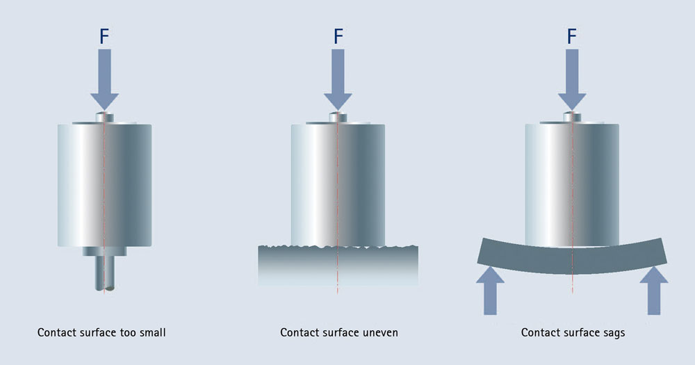
If a force transducer is installed without a thrust piece of this type, the following requirements must be met for the component that comes in contact with the convex force application area:
  • HBM recommends a hardness of at least 43 HRC
  • The workpiece should be ground
  • Mounting must be performed so that the mating component does not lift up and the transducer could be struck by impacts
  • If possible the mating component should rotate and have a swivel bearing to prevent bending moments and torques.
Force transducers are generally placed in the structure for their application. This means that the force is directed into the structure under the force transducer. However, horizontal mounting is also conceivable. In this case the transducer should be rigidly connected with the structure. In any case the structural element on which the bottom of the transducer is mounted must be designed so that forces are received with only slight deformation. Sufficient rigidity should be ensured for this purpose. It is also important for the surface to be even. The maximum tolerable unevenness is 0.005 mm. An even substrate structure ensures that the force transducer will be deformed in the way that is required to achieve the manufacturer's full measurement accuracy. The substrate structure should be resistant to deformation and must have a larger diameter than the force transducer. A substructure that results in significant deformation, too small a surface or unevenness in the application of force will lead to states of deformation that were not taken into consideration in the design of the transducer. Technical data related to sensitivity, linearity and hysteresis may therefore change.

4. Force transducers for tensile and compressive forces with screw-on application of force

"If tensile forces will be measured in addition to compressive forces, convex load application is naturally unsuitable. For tensile force transducers or force transducers that are suitable for tensile and compressive forces, the components that apply the force to the transducer are therefore screwed together with the transducer. Some force transducers, for example the Z4A or U2B, have an external thread on the top and an internal thread on the bottom. Force transducers of series U10M and U10S are fitted with internal threads on both connection sides. Internal threads are considerably more compact. This makes them suitable for force transducers that must be flat. In external threads the distance between the screw connection and SG installation is naturally greater, which has a positive effect on various metrological properties (hysteresis!). Force transducers for tensile and compressive loading with very high requirements for accuracy and reproducibility therefore generally have an external thread. An internal thread is only used on the non-critical side. For internal thread: For every bolted connection of a force transducer, sufficient surface pressure must be exerted on the force transducer by the nut.

There are two different ways to do this:

a.    A bolted connection with application of force that is greater than the largest operating force

  • Screw the connecting elements into the force transducer on both sides.
  • Load the force transducer beyond its operating load (do not exceed the maximum limits)
  • Hand-tighten the locknuts
  • Now the force can be received by the transducer. The sensor is correctly mounted for the required overload see the mounting instructions.

b.    Mounting with suitable torque

  • Screw in the connecting elements
  • Tighten the locknuts according to the torques specified in the mounting instructions

Note that the torque required for mounting must never be applied through the transducer. If it is, the transducer may be destroyed. For force transducers with external thread: The component to be connected must at least be fixed in place by a locknut. This requirement is eliminated for purely static force measurements. The torques are specified in the operating manuals for the force transducers. ; The Z4A (right) is only locked on the internal thread. Locking with a nut is always required for the external thread of the U2B (left) HBM offers knuckle eyes for almost all transducers that are suitable for tensile and compressive forces. If force transducers are mounted using at least one knuckle eye, torsional moments are not applied to the transducer. If two knuckle eyes are used, bending moments and forces must not be applied to the force transducer at an angle.   Use of two knuckle eyes for calibration of a U10M with a maximum capacity of 500 kN Knuckle eyes are normally not suitable for measuring dynamic forces because bearing play increases over time, which can lead to measurement errors. Furthermore, the frequency range within which knuckle eyes can be used is limited to about 10 Hz. For dynamic requirements we therefore recommend the use of pliable elements to apply forces."

Related content