arrow_back_ios

Main Menu

See All Software See All Instruments See All Transducers See All Vibration Testing Equipment See All Electroacoustics See All Acoustic End-of-Line Test Systems See All Academy See All Resource Center See All Applications See All Industries See All Services See All Support See All Our Business See All Our History See All Global Presence
arrow_back_ios

Main Menu

See All Analysis & Simulation Software See All DAQ Software See All Drivers & API See All Utility See All Vibration Control See All High Precision and Calibration Systems See All DAQ Systems See All S&V Hand-held Devices See All Industrial Electronics See All Power Analyzer See All S&V Signal Conditioner See All Acoustic Transducers See All Current and Voltage Sensors See All Displacement Sensors See All Force Sensors See All Load Cells See All Multi Component Sensors See All Pressure Sensors See All Strain Sensors See All Strain Gauges See All Temperature Sensors See All Tilt Sensors See All Torque Sensors See All Vibration See All Accessories for Vibration Testing Equipment See All Vibration Controllers See All Measurement Exciters See All Modal Exciters See All Power Amplifiers See All LDS Shaker Systems See All Test Solutions See All Actuators See All Combustion Engines See All Durability See All eDrive See All Production Testing Sensors See All Transmission & Gearboxes See All Turbo Charger See All Training Courses See All Acoustics See All Asset & Process Monitoring See All Custom Sensors See All Durability & Fatigue See All Electric Power Testing See All NVH See All Reliability See All Vibration See All Weighing See All Automotive & Ground Transportation See All Calibration See All Installation, Maintenance & Repair See All Support Brüel & Kjær See All Release Notes See All Compliance
arrow_back_ios

Main Menu

See All nCode - Durability and Fatigue Analysis See All ReliaSoft - Reliability Analysis and Management See All API See All Experimental Testing See All Electroacoustics See All Noise Source Identification See All Environmental Noise See All Sound Power and Sound Pressure See All Noise Certification See All Industrial Process Control See All Structural Health Monitoring See All Electrical Devices Testing See All Electrical Systems Testing See All Grid Testing See All High-Voltage Testing See All Vibration Testing with Electrodynamic Shakers See All Structural Dynamics See All Machine Analysis and Diagnostics See All Dynamic Weighing See All Vehicle Electrification See All Calibration Services for Transducers See All Calibration Services for Handheld Instruments See All Calibration Services for Instruments & DAQ See All On-Site Calibration See All Resources See All Software License Management

The Design of High-Pressure Transducers

null

What Makes High-Pressure Transducers so Special?

Pressure sensors are based on a measuring body that must be able to tolerate high loading, especially in the high-pressure range. The design and the material used are key factors for the measuring body’s accuracy, reliability, and service life.

The monolithic design of pressure sensors used in the high-pressure range

High-pressure transducers are generally designed as thick-walled tubes (see fig. 1) and are made of a single piece of steel. Therefore, their design is also called “monolithic”. The term “monolithic” is derived from Greek and means “a single stone” (mono- = single; lithos = stone).

null

The monolithic measuring body design ensures especially low stress gradients and stress peaks.  Furthermore, these measuring bodies have a long service life, since they have no weld seams or other weak points. Fig. 2 shows various pressure-hole designs in the schematic layout, while fig. 3 displays a choice of different measuring bodies.

null
null

The advantages of this design

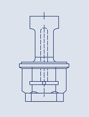
The mechanical stress at the internal diameter Di is significantly higher than at the external diameter Da. Therefore, this is the point subjected to the highest loading due to the triaxial stress state (see fig. 4).

null

Postulated by strength theory, the reference stress σv must be derived from the three stresses σt (tangential stress), σr (radial stress), and σn (normal stress) to allow an assessment of the service life. The reference stress is then correlated with the material’s characteristic values.

Transducers used in the ultra-high-pressure range (>10,000 bar) are designed such that the material’s yield point is exceeded at the internal fiber, which is subjected to the highest loading. This does not mean that the transducer will be torn apart, since the outer layers of the measuring body still “bear” the pressure very well. If the pressure is increased still further, the place at which the yield point is exceeded moves slowly outward inside the wall. The transducer would only break when the yield point has moved to the outermost layer. 

The ratio of internal diameter to external diameter (Da/Di), and thus the thickness of the wall, must be chosen so that the dynamic properties of the spring steel can be fully utilized, and the maximum capacity for load changes is reached.

If cleverly implemented, this design offers the advantage of optimally utilizing the material in terms of its endurance strength values.

Selecting materials is a compromise

Selecting materials involves a compromise between the maximum service life under dynamic loading and the metrological properties that can be achieved by the spring element. Steels that appear to be excellent materials for high-pressure applications due to a high yield point can have unsuitable spring properties that will result in too large a hysteresis. This means that the material will show different characteristic curves for increasing and decreasing stress, which results in measurement inaccuracies.  Spring element materials with a low hysteresis have a tensile strength of > 1GPa, which makes them far more suitable for high-pressure applications.

Steels commonly used by pressure transducer manufacturers have a dynamic load-carrying capacity for endurance fatigue of about 600 MPa, which is equivalent to a compressive loading of approximately 6,000 bar. Pressure-bearing parts exposed to repeated loading of 6,000 to 7,000 bar cannot exhibit endurance strength. This is illustrated in fig. 5. The schematic representation of a Wöhler diagram shows the tensile strength Rm as a function of the number of alternating loads and the compressive stress σD.

null
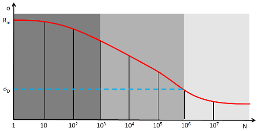
  • Low-cycle endurance: Stress amplitudes at which damage (breakage) occurs at N<10³ alternating loads

  • Static strength: Stress amplitudes at which damage (breakage) occurs at 10³<N<106 alternating loads

  • Endurance strength: Stress amplitudes at which damage (breakage) does not occur with any number of alternating loads, 2 x 10⁶ ≥ N ≥ 107

Besides the material properties, several other factors influence service life.  Furthermore, post-treatment of the transducer also helps ensure that pressure values exceeding 6,000 bar can be reliably measured.

*SG = strain gauge

Related Content