IEPE/ICP transducer IEPE/ICP transducer | HBM

IEPE / ICP® transducer to PMX over an external Smart Module

This is a quickstart guide to connecting an IEPE / ICP transducer to a PMX system via an External Smart Module.

Introduction

A “current-fed piezo electric transducer - short name IEPE or ICP®“ is connected to a voltage input channel of a PMX module using HBM’s External Smart Module (EICP) which works as a signal conditioner between the transducer and the standardized voltage input of +/- 10 V.

The EICP Smart Module needs a 24 V DC active power supply and comes along with a BNC connector. The following amplifiers offer standard +/- 10 V inputs and an active power supply of 24 V DC: PX401

The following parts are necessary:

  • Smart Module: 1-EICP-B-2 (BNC connector to IEPE sensor)
  • Cable to SubHD: 1- SAC-EXT-MF-x-2 (x = cable length in meters)

A variant called 1-EICP-M with microdot connector is also available.

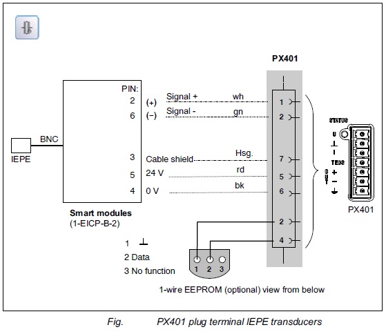
Connecting the Smart Module to PX401

  • The figure below shows the connection between the Smart Module and a PX401 Module.

Transducer

  • Sensor used in this example: DYTRAN Model 3055B3T (accelerometer)


Specifications of 3055B3T

TEDS-Transducer Electronic Data Sheet

TEDS can be used for automatic transducer identification and can be installed in the form of a small EEPROM TEDS chip in the plug. Once the adapter has been prepared accordingly, only the transducer identified by TEDS may be used; using different transducers might lead to incorrect results.


Writing TEDS data to the EEPROM chip

  • Connect Smart Module with sensor to PMX amplifier
  • Open TEDS Editor on specific channel
  • Select ”High Level Voltage Output Sensor“ template and configure
    • Physical measurand: Acceleration (m2/s or g)
    • Electrical range: standard +/- 10 V
    • Power requirements: required
    • Fill out rest of data sheet according to your transducer

PMX Settings

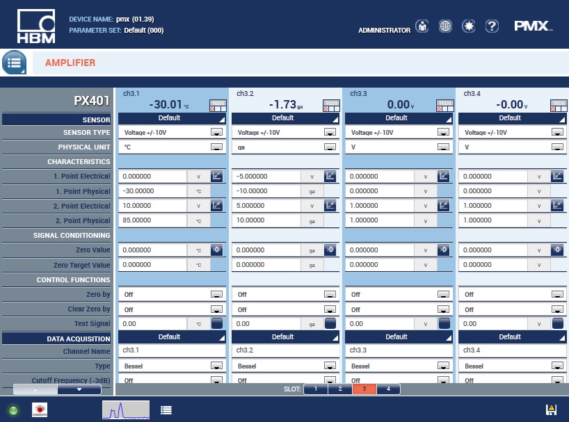
  • For the Accelerometer example the following settings are applied in the PMX WebBrowser. (Please note: physical unit = ga)
  • Settings for 1st/2nd Point Electrical and Physical see Specifications of the transducer (orange row)

Disclaimer

This example is simply for the purpose of illustration. It cannot be used as the basis for any warranty or liability claims.