

arrow_back_ios
See All Products
See All Knowledge
See All Solutions
See All Services & Support
See All About
See All Contact Us
Main Menu
arrow_back_ios
See All Software
See All Instruments
See All Transducers
See All Vibration Testing Equipment
See All Electroacoustics
See All Acoustic End-of-Line Test Systems
See All Academy
See All Resource Center
See All Applications
See All Industries
See All Services
See All Support
See All Our Business
See All Our History
See All Global Presence
Main Menu
- High Precision and Calibration Systems
- DAQ Systems
- S&V Hand-held Devices
- Industrial Electronics
- Power Analyzer
- S&V Signal Conditioner
- Acoustic Transducers
- Current and Voltage Sensors
- Displacement Sensors
- Force Sensors
- Load Cells
- Multi Component Sensors
- Pressure Sensors
- Strain Sensors
- Strain Gauges
- Temperature Sensors
- Tilt Sensors
- Torque Sensors
- Vibration
- Accessories for Vibration Testing Equipment
- Vibration Controllers
- Measurement Exciters
- Modal Exciters
- Power Amplifiers
- LDS Shaker Systems
- Accessories for Electroacoustics Applications
- Artificial Ear
- Artificial Mouth
- Bone Conduction
- Data Acquisition
- HATS (Head and Torso Simulator)
- Microphone
- Signal Conditioning
- Test Solutions
- Accessories for Acoustic End-of-Line Test Systems
- Actuators
- Combustion Engines
- Durability
- eDrive
- Mobile Systems
- Production Testing Sensors
- Transmission & Gearboxes
- Turbo Charger
- Application Notes
- Articles
- Case Studies
- Recorded Webinars
- Presentations
- Primers and Handbooks
- Videos
- Search all resources
- Acoustics
- Asset & Process Monitoring
- Custom Sensors
- Data Acquisition & Analysis
- Durability & Fatigue
- Electric Power Testing
- NVH
- Reliability
- Vibration
- Virtual Testing
- Weighing
arrow_back_ios
See All Analysis & Simulation Software
See All DAQ Software
See All Drivers & API
See All Utility
See All Vibration Control
See All High Precision and Calibration Systems
See All DAQ Systems
See All S&V Hand-held Devices
See All Industrial Electronics
See All Power Analyzer
See All S&V Signal Conditioner
See All Acoustic Transducers
See All Current and Voltage Sensors
See All Displacement Sensors
See All Force Sensors
See All Load Cells
See All Multi Component Sensors
See All Pressure Sensors
See All Strain Sensors
See All Strain Gauges
See All Temperature Sensors
See All Tilt Sensors
See All Torque Sensors
See All Vibration
See All Accessories for Vibration Testing Equipment
See All Vibration Controllers
See All Measurement Exciters
See All Modal Exciters
See All Power Amplifiers
See All LDS Shaker Systems
See All Test Solutions
See All Actuators
See All Combustion Engines
See All Durability
See All eDrive
See All Production Testing Sensors
See All Transmission & Gearboxes
See All Turbo Charger
See All Training Courses
See All Acoustics
See All Asset & Process Monitoring
See All Custom Sensors
See All Durability & Fatigue
See All Electric Power Testing
See All NVH
See All Reliability
See All Vibration
See All Weighing
See All Automotive & Ground Transportation
See All Calibration
See All Installation, Maintenance & Repair
See All Support Brüel & Kjær
See All Release Notes
See All Compliance
Main Menu
- Vibration Control Software
- Random
- Classical Shock
- Time Waveform Replication
- Sine-On-Random
- Random-On-Random
- Shock Response Spectrum Synthesis
- Strain Gauge Precision Instrument
- Bridge Calibration Units
- Microphone Calibration System
- Vibration Transducer Calibration System
- Sound Level Meter Calibration System
- Sound Level Meters
- Vibration Meters
- Sound Intensity Meter
- Noise Dosimeter
- Hand-held Software
- Accessories for S&V Hand-held Services
- Multi Channel System
- Single Channel System
- Piezoelectric (Paceline)
- Press Fit Controller
- Amplifier with Display
- Legal for Trade
- Accessories for Industrial Electronics
- Microphone Cartridges
- Microphone Pre-Amplifiers
- Microphone Sets
- Hydrophones
- Sound Sources
- Acoustic Calibrators
- Special Microphones
- Accessories for Acoustic Transducers
- Industrial / Experimental / Test Rig Use
- Reference (Transfer Standards, Fulfils ISO376)
- Customized Force Sensors
- Accessories for Force Sensors
- Single Point
- Bending / Beam
- Canister
- Tension
- Compression
- Weighing Modules
- Customized Load Cells
- Accessories for Load Cells
- Piezoelectric Charge Accelerometer
- Piezoelectric CCLD (IEPE) Accelerometers
- Force Transducers
- Piezoelectric Reference Accelerometer
- Tachometer Probes
- Vibration Calibrators
- Optical Accelerometer
- Accessories for Vibration Transducers
- Discontinued - Vibration Transducers
- High-Force LDS Shakers
- Medium-Force LDS Shakers
- Low-Force LDS Shakers
- Permanent Magnet Shakers
- Shaker Equipment / Slip Tables
- Acoustics and Vibration
- Asset & Process Monitoring
- Data Acquisiton
- Electric Power Testing
- Fatigue and Durability Analysis
- Mechanical Test
- Reliability
- Weighing
- Electroacoustics
- Noise Source Identification
- Environmental Noise
- Sound Power and Sound Pressure
- Noise Certification
- Acoustic Material Testing
- OEM Custom Sensor Assemblies for eBikes
- OEM Custom Sensor Assemblies for Agriculture Industry
- OEM Custom Sensor Assemblies for Medical Applications
- Custom Sensor Assemblies for Robotic OEM
- Durability Simulation & Analysis
- Structural Durability and Fatigue Testing
- Material Fatigue Characterisation
- Electrical Devices Testing
- Electrical Systems Testing
- Grid Testing
- High-Voltage Testing
- End-of-Line (EoL) & Durability Testing
- Calibration Services for Transducers
- Calibration Services for Handheld Instruments
- Calibration Services for Instruments & DAQ
- On-Site Calibration
- Resources
arrow_back_ios
See All nCode - Durability and Fatigue Analysis
See All ReliaSoft - Reliability Analysis and Management
See All API
See All Experimental Testing
See All Electroacoustics
See All Noise Source Identification
See All Environmental Noise
See All Sound Power and Sound Pressure
See All Noise Certification
See All Industrial Process Control
See All Structural Health Monitoring
See All Electrical Devices Testing
See All Electrical Systems Testing
See All Grid Testing
See All High-Voltage Testing
See All Vibration Testing with Electrodynamic Shakers
See All Structural Dynamics
See All Machine Analysis and Diagnostics
See All Dynamic Weighing
See All Vehicle Electrification
See All Calibration Services for Transducers
See All Calibration Services for Handheld Instruments
See All Calibration Services for Instruments & DAQ
See All On-Site Calibration
See All Resources
See All Software License Management
Main Menu
- Testing Of Hands-Free Devices
- Smart Speaker Testing
- Speaker Testing
- Hearing Aid Testing
- Headphone Testing
- Telephone Headset And Handset Testing
- Acoustic Holography
- Underwater Acoustic Ranging
- Wind Tunnel Acoustic Testing – Aerospace
- Wind Tunnel Testing For Cars
- Beamforming
- Flyover Noise Source Identification
- Real-Time Noise Source Identification With Acoustic Camera
- Sound Intensity Mapping
- Spherical Beamforming
- Product Noise
- Foundation Monitoring Using Strain Gauges
- Monitoring Solutions for Bridges
- Monitoring Solutions for the Oil and Gas Industry
- Wind Turbine Testing and Condition Monitoring
- Tunnel Monitoring with Optical Sensor Technology
- Shock and Drop Testing
- Environmental Stress Screening - ESS
- Package Testing
- "Buzz, Squeak and Rattle (BSR)"
- Mechanical Satellite Qualification
- Operating Deflection Shapes (ODS)
- Classical Modal Analysis
- Ground Vibration Test (GVT)
- Operational Modal Analysis (OMA)
- Structural Health Monitoring (SHM)
- Test-FEA Integration
- Shock Response Spectrum (SRS)
- Structural Dynamics Systems
- Electrification - Statistical and reliability aspects (NEW)
- Electrification - Electrical and signal processing aspects (NEW)
- Electrification - Mechanical and durability aspects (NEW)
- Electrification (NEW) - Designing and Testing the Endurance of Structural Components for Electric Vehicles
- "Electrification (NEW) - Electrification: Ensuring the Durability, Reliability and Performance of Electric Vehicles"
- Electrification (NEW) - Electrical and Signal Post-Processing Techniques for AC Power Analysis in Electric Vehicles
- Electrification (NEW) - Applying Statistical and Reliability Techniques for Determining Battery Life in Electric Vehicles
- Force Calibration
- Torque Calibration
- Microphones & Preamplifiers Calibration
- Accelerometers Calibration
- Pressure Calibration
- Displacement Sensor Calibration
- Sound Level Meter Calibration
- Sound Calibrator & Pistonphone Calibration
- Vibration Meter Calibration
- Vibration Calibrator Calibration
- Noise Dosimeter Calibration
- QuantumX Calibration
- Genesis HighSpeed Calibration
- Somat Calibration
- Industrial Electronics Calibration
- LAN-XI Calibration
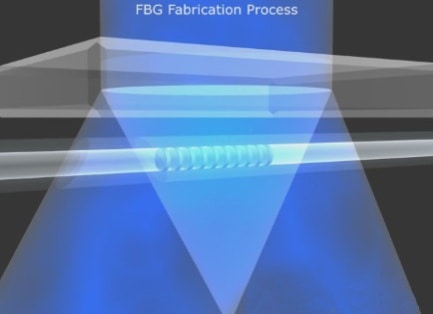
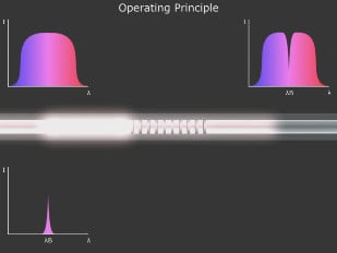
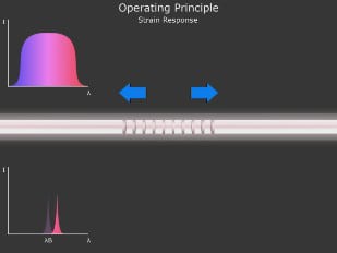
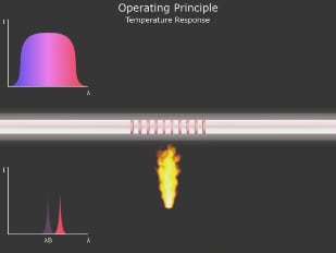


 Equation 2
Where:
k – k factor of the Bragg grating
 Equation 3
 Equation 4
 Equation 5
Where:
 Equation 6
 Equation 7


