PMX CASMA-filter for angle-related filtering PMX CASMA-filter for angle-related filtering | HBM

Tips for use: PMX CASMA filter

Brief description

These instructions describe how to use a special filter for averaging of a noisy torque signal.
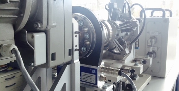
The CASMA filter (Crank Angle Sampled Moving Average) works in angular synchronism and is time independent, thus allowing to automatically respond to RPM changes. The PMX provides a calculated channel especially for this purpose. A simple example demonstrates how to use CASMA filter with a T40B torque transducer mounted to a 5-cylinder.

Basics

Due to a combustion engine’s stroke involving compression and expansion in the individual cylinders and the corresponding fluctuations in combustion, the torque generated by an engine exhibits highly dynamic behavior. These disturbances  are systemic and can significantly affect the desired measurement.

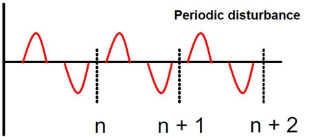
The CASMA filter eliminates periodic disturbances that are synchronous with the rotation of a shaft. It uses a moving average. The filter does not work time synchronously as usual. It rather works synchronously with the shaft rotation. Thus the filter effect does not depend on the rotation speed.


The filter’s calculation period is proportional to the rotation speed. When the rotation stops, the filter stops operating as well.

The CASMA filter

Create a calculated channel

Create a new calculated channel “rotation synchronous filter” in the Analysis category.

Adjust parameters

  • Filter input: Enter the signal to be filtered here.
  • Shaft Angle Input: Enter the signal of the angle of rotation sensor here. The measured values must be between 0° and 360°.
  • Window Width: Specify the range for taking the moving average. The width must be between 30° and 720°. The default setting is 180°. The ratio of the window width to the resolution must be less than 180.

The window width can be easily determined experimentally by projecting the periodic time on the disturbance to the angle of rotation (see screenshot). In this example, there is a periodic disturbance every 720°.
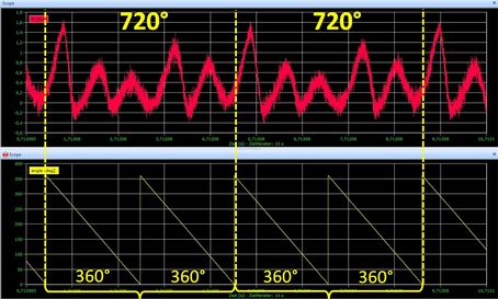
  • Minimum Speed: This virtual rotational speed is applied when the active rotational speed is less than the defined minimum rotational speed.
  • Resolution: This value determines how often (how many degrees each time) a new average will be calculated. Note that the maximum permitted permissible rotational speed depends on this value because the speed of calculation is determined by the overall update rate.

The theoretical value is derived by: Maximum rotational speed = resolution * overall update rate / 6.

For practical purposes you should use values that amount to only 10 to 20% of this theoretically possible maximum rotational speed.

Resolution

The theoretical maximum rotational speed at an overall update rate of 19,200 Hz

The theoretical maximum rotational speed at an overall update rate of 38,400 Hz

3200 rpm

6400 rpm

6400 rpm

12,800 rpm

12,800 rpm

25,600 rpm

19,200 rpm

38,400 rpm

25,600 rpm

51,200 rpm

The following multiples of the rotational speed are suppressed depending on the window width:

Window width

Multiples

90°

4, 8, 12, …

120°

3, 6, 9, …

180°

2, 4, 6, …

360°

1, 2, 3, …

720°

0, 5, 1, 1, 5, …


Note: If one of the source signals is invalid, the output signal will be invalid as well.

CASMA in action

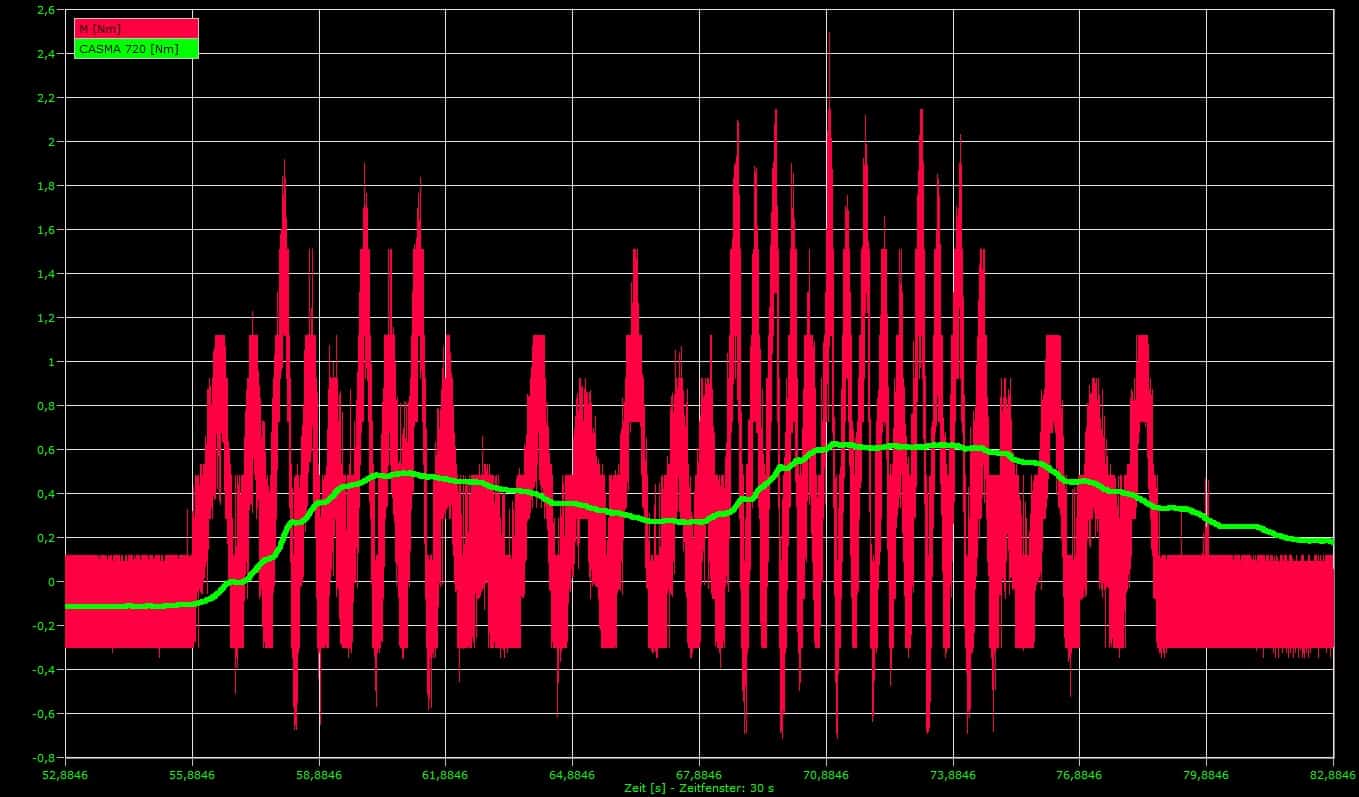
Unfiltered torque signal (red), torque signal filtered using CASMA (green).
It can be clearly seen that the CASMA filter achieves excellent stabilization of torque measurements in correlation to the engine speed, which also changes over time. The greater the width of this filter, the better the results.
Example

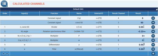
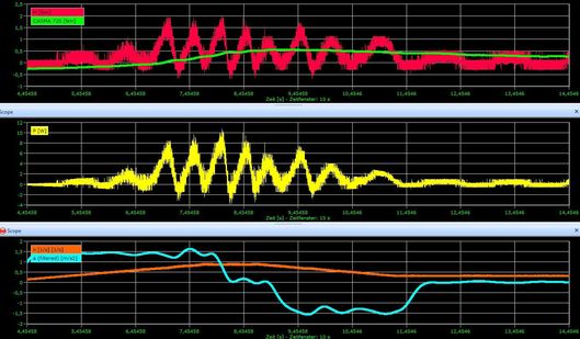
In this short example, PMX is used for analyzing power P[W], rotational speed n [1/s] and acceleration [1/s²], in addition to torque M [Nm] and the corresponding CASMA filter. The calculated channels as shown in the screenshot below have been created for this purpose. The signals are displayed in catman.

Calculations:

Power:

Angular speed:


Angular acceleration:

Important: For all calculations the rotation speed n has to be converted from revolutions per minute to revolutions per second, i.e. divided by 60.

Channels

Please see below for all channels displayed graphically in catman. The colors in brackets refer to the colors of the curves. The signals consist of the following channels:
Torque M (red):

  • Directly from the measurement channel of the PX460

CASMA filter (green):

  • Already explained in detail

Power P (yellow):

  • Divider (rotational speed n / 60), revolutions per second
  • Constant signal (2*pi)
  • Multiplier (M * n [1/s] * 2*pi]

Rotational speed n (orange):

  • Directly from the measurement channel of the PX460

Angular acceleration (blue):

  • Multiplier (2*pi * n [1/s]), results in the angular speed w
  • Differentiator (w)

Disclaimer

These examples are for illustrative purposes only. They cannot be used as the basis for any warranty or liability claims.