Communication via FTP from/to catman software Communication via FTP from/to catman software | HBM

CODESYS Application – catman–PMX communication

These instructions describe how to create a CODESYS application for PMX. Basic experience with CODESYS is assumed. Experienced users are free to adopt a different approach. Further help is available from the examples that are installed as standard on the desktop when the PMX package is installed and from the online help for the package.

The necessary files can be found on the "PMX CODESYS" CD that is included in the scope of supply of every PMX containing CODESYS or can be downloaded from the support page at hbm.com.

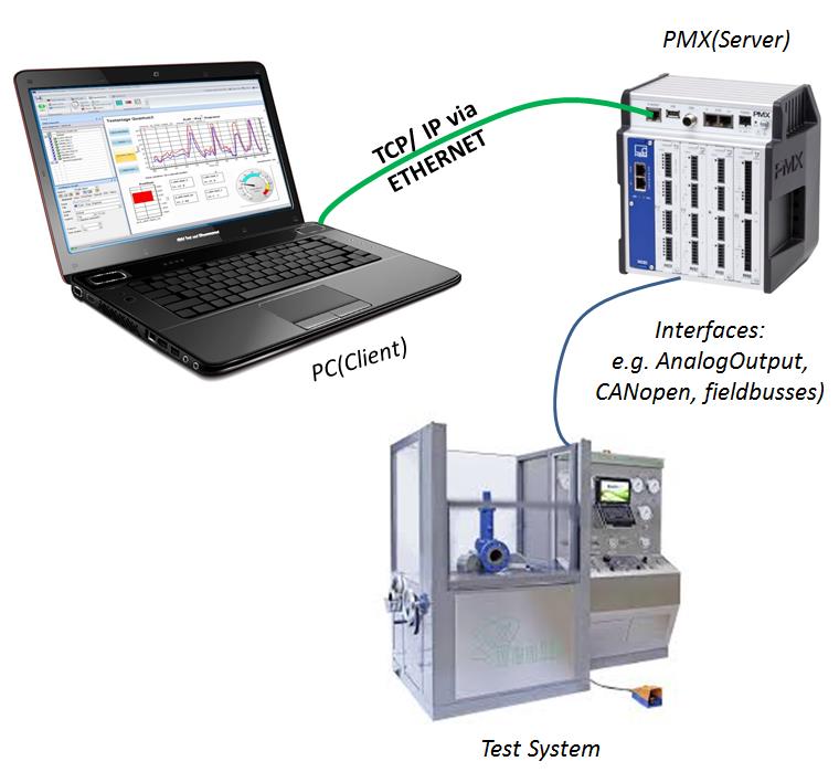
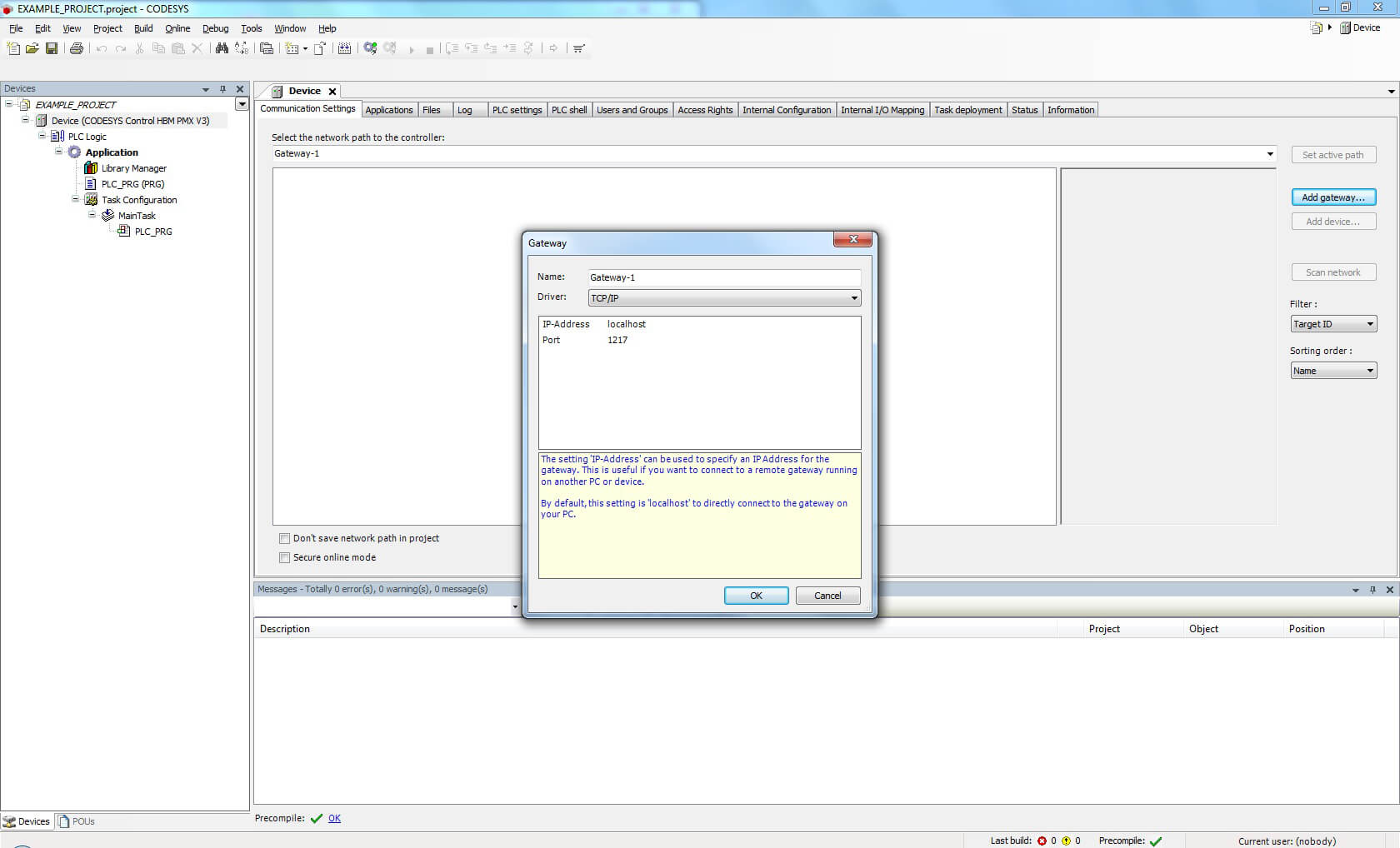
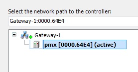
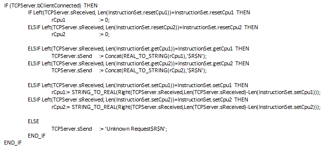
In this particular example PMX is used as a TCP/IP server and communication with HBM’s catman AP is built up.

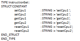
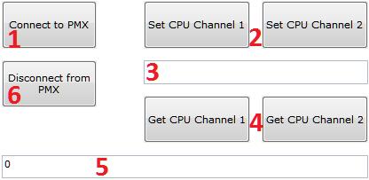
catman AP enables CPU channels to be set using customized commands, for example, to change PID setpoint values or similar. Therefore, simple automated control systems can be implemented using PMX from HBM.

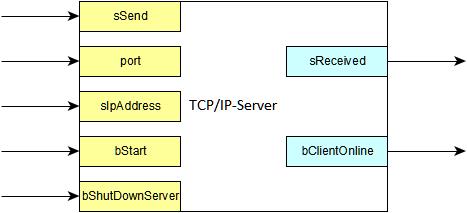
The basic functionality of the TCP/IP server on the PMX is explained in the corresponding Tips for use from HBM. The string manipulations in this example have been made using the provided OSCAT libraries (www.oscat.de

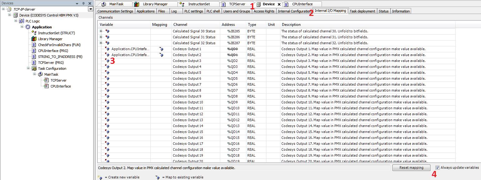
).On the PMX side, the example mainly consists of the TCP/IP server and the CPU interface. Communication functions on the PC are provided by a catman Easy script.

Extract CODESYS package

Open the development environment
Run CODESYS software as admin.

Extract package

Connect PMX

Add gateway

Double-click “Device (CODESYS Control HBM PMX V3)“ and then press “Add gateway…“ on the right-hand margin. Keep the default settings and confirm by pressing “OK”.

Integrate PMX

The “Scan network” function should automatically detect the PMX. Activate the device by double-clicking it.

Command interpretation on the PMX by CODESYS

The TCP/IP server is used as a black box. After catman AP has successfully built up a connection with it, the server transmits strings received to the CPU interface that interprets the commands and operates accordingly.

As an introduction to the example the server interfaces are shown at first. Then, we take a closer look at command interpretation and explain connection to the CPU channels that can be used for further processing. Two channels are set in this way in this example.

Server interfaces

  • Inputs:
    • sSend (String: String to be sent)
    • port (Word: Port on which the PMX can be addressed)
    • sIpAddress (String: IP-address that has to be adjusted to the IP-address shown in the webbrowser)
    • bStart (Boolean: Starts the server)
    • bShutDownServer (Boolean: Stops the server)
  • Outputs:
    • sReceived (String: String received)
    • bClientOnline (Boolean: Signals identification of a client)

Functionality of the CPU interface

The provided CPU interface supports three commands each for every channel: set, get, reset. The commands are combined in the “instructionSet" struct to provide a quick overview of the functions for the user. Please note that the “set…” commands end with a space here – this makes it easier to distinguish between the actual command and the following parameter to be set.

When the TCP server detects a connection to a client, i.e. catman AP, the CPU interface starts checking incoming messages in sReceived for commands. Once a command is detected, they are applied.

The behavior that is triggered by the command has to be determined in the CPU interface.

Values to be returned to catman AP have to be terminated with the string “$R$N”. To achieve this, the return value is concatenated with “$R$N” into one string using the string command “Concat()”.

Assignment to the CPU channels

The assignment of variables to the CPU channels is implemented in the CODESYS development environment as follows:

  • Double-click “Device” in the left-hand directory tree of the development environment to open the corresponding configuration window
  • Click the “Internal I/O Mapping“ tab. (2)
  • Scroll to „Codesys Output x“ and double-click the empty field in the “Variable” column. (3)
  • Select the variable of your choice in the window that opens(the variable must be of type REAL!)
  • Finally check the “Always update variables“ box in the bottom right corner. (4)

catman AP

A catman Easy script has to be created in catman AP, which is capable of creating a TCP/IP client by means of the object library “EA_Comm” and of handling the defined commands in CODESYS. Of course, any other TCP/IP client also can establish a connection to the PMX and communicate via commands.

The example provides a visualization with several buttons that enable a connection to be established step by step. The buttons should be operated in the sequence stated below: connect to PMX, set or get values as required, disconnect from PMX. Should a problem occur, disconnecting and then reconnecting the PMX usually helps.

A value in field (5) that is not equal to zero signals the user that there is a problem.

Use the “Connect to PMX” button (1) to start building up a connection. If the PMX has successfully been connected, “Ready” is shown in field (3). The connected CPU channels 1 and 2 can be set (2) and got (4) in field (3) from now on. The user has to make sure that the values set are inside the specific range of values of the PMX. Otherwise, the CPU channel will be set, however, the connected hardware cannot process the invalid value. Furthermore, there has to be a value in field (3), otherwise a zero will be set automatically on the channel.

Return values are also displayed in field (3). Field (5) does only provide error detection within the script. As soon as a displayed value is not equal to zero, disconnect and then reconnect. After parameterization of the channels, the connection should always be disconnected (6).

The script code allows to understand how the “EA_Comm” library is used for installation of a TCP/IP client. The corresponding routines or rather subs are triggered by the buttons in the visualization. The following extract deals only with setting CPU channel 1. However, the sub-methods can be transferred to CPU channel 2.

The “Timeout” variable defines the waiting period for a response from the server. The time should always be longer than the cycles of the PLC. “Id“ provides a handle or descriptor for managing the subjacent sockets. “Terminator“ defines the ASCII character up to which messages in the buffer are read – char 10 stands for “Linefeed”, which is equivalent to “$R$N” in CODESYS. The buffer size is defined by “MaxBytes” and should match the buffer size in the PMX. The same applies for the port number and the IP address, of course.

Please note that the receive buffer is not automatically emptied by the library. I.e., when reading again after successfully reading a message, all remaining bytes of the previous message, which do not include any relevant information, are read. The problem is solved by reading the buffer byte by byte until it is empty. The corresponding part is marked in the sub “getCPU1”.

TIP

Further information and help with creating Codesys programs is available from the Codesys online Help, on the Internet at https://www.codesys.com/ or in the Codesys chat room https://forum.codesys.com/
Benefit from the knowledge and information available from the Codesys Store. You'll find many examples of programs and solutions there, covering a wide range of tasks https://store.codesys.com/

Disclaimer

These examples are simply for the purpose of illustration. They cannot be used as the basis for any warranty or liability claims.