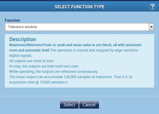
These instructions describe how to create a tolerance window in the PMX that can be used for a component or performance test for example. Several of those tolerance window analyses can be used at the same time. In principle, the limits of the tolerance window as well as the start and stop condition can be defined statically or using variable signals, a PLC or PC software. Those parameters can be changed at runtime resulting in a “dynamic” measurement window.
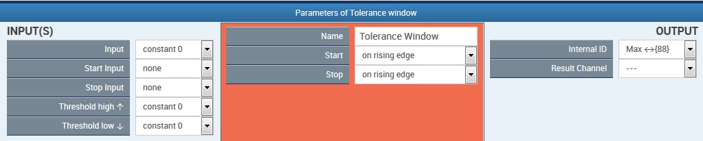
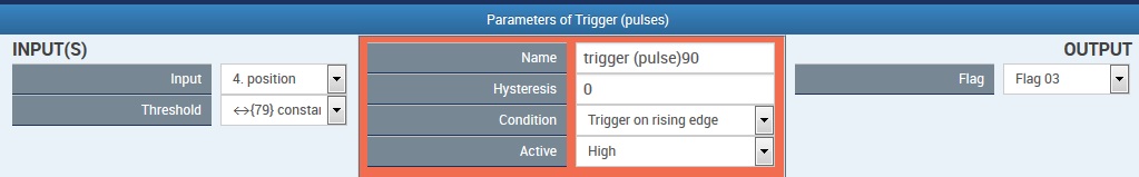
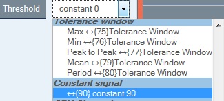
In this particular example a tolerance window is triggered by a rotary encoder during a force measurement. When the rotary angle reaches a value of 90° the window is started. When rotating 180° back to a value of -90° (or 270°) the measurement is stopped.
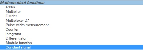
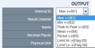
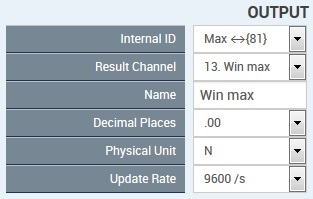
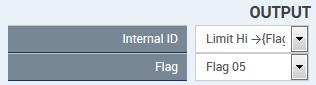
The upper and lower limit of the window each is defined by a constant; however a variable value is possible, too. If the upper or lower limit is exceeded during a run, a flag for signalization is set. Furthermore it is possible to display various measurement values within a window.
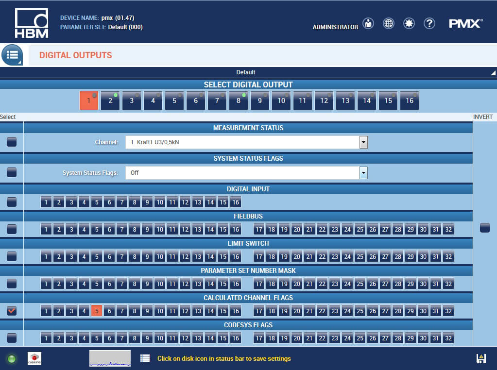
All those values and flags can be further processed through the analog/digital interfaces as well as through Ethernet and field bus. This allows automation of testing tasks.