Aug 29 2019
Optical Strain Sensor Fundamentals
Read More
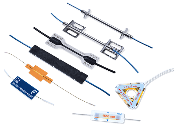
Optical strain gauges are strain sensors based on optical fibers. There are several optical technologies that fit the same classification, but this article focuses on Fiber Bragg Grating (FBG) based sensors – a technology embraced by HBK. FBGs are primarily used to measure strain, but can easily be integrated into different types of transducers, such as temperature, acceleration or displacement transducers.
Compared to traditional electrical strain gauges, optical strain gauges do not need electricity. Instead, the technology is based on light that propagates through a fiber. The sensors are, therefore, completely passive and immune, for example, to electromagnetic interference. This is just one of the reasons why optical strain gauges are superior to electrical ones in certain applications.
Cristina Barbosa, Product Manager for HBK optical technology, about optical strain gauges:
“When people need to measure strain, they first think of electrical strain gauges. Optical strain gauges can come in handy, though, where electrical ones could cause difficulties, for example due to environmental conditions.”
In this article, we will focus on intrinsic fiber optic strain sensors, where the fiber itself is the sensor. Other types of measuring technologies use the fiber itself to transmit light, not to measure with it.
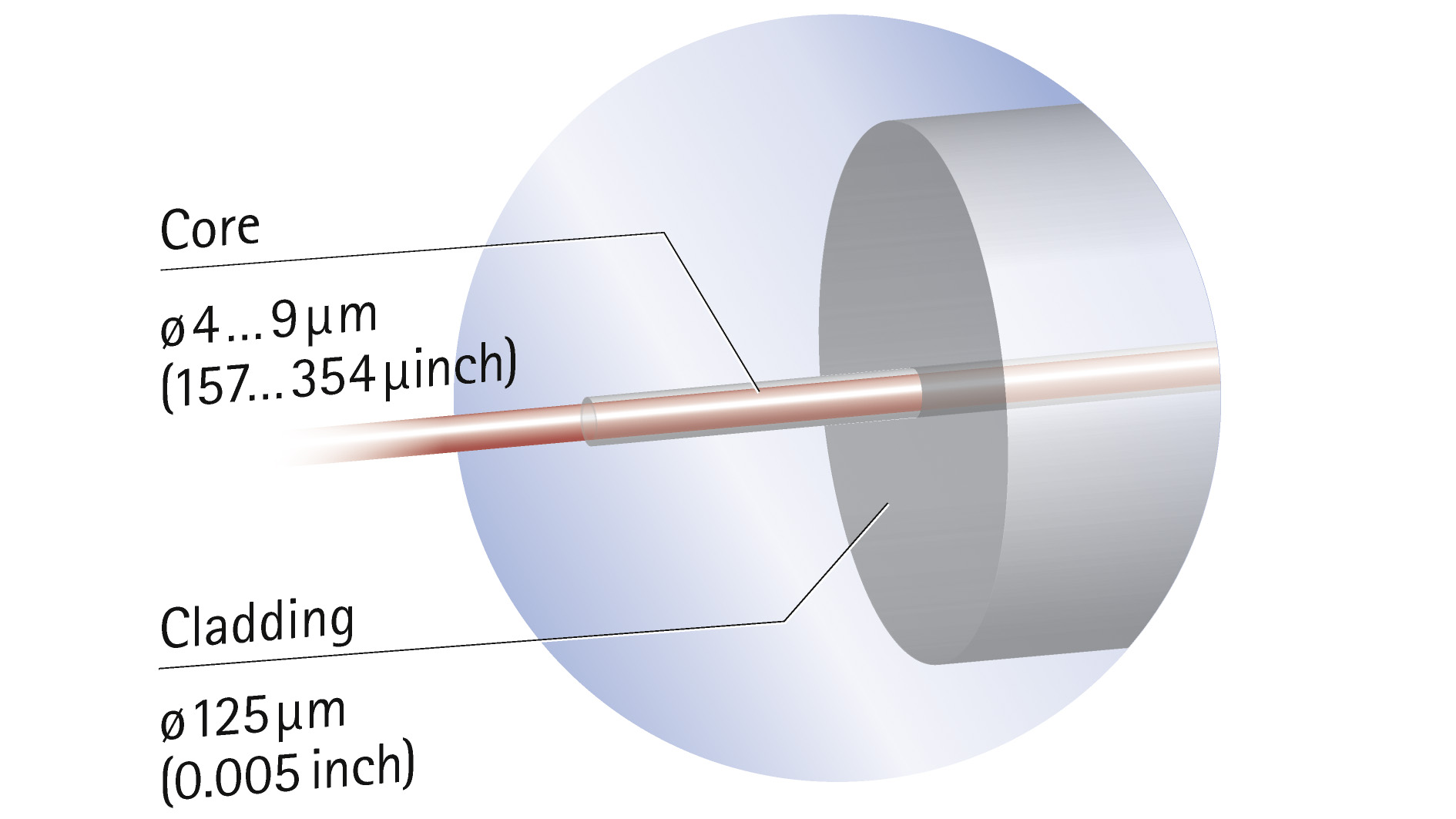
An optical fiber usually consists of a glass or silica fiber and a polymer coating. It is much like regular telecommunication fiber and can be up to several kilometres long with many measuring points along its length. The fiber itself consists of two layers: the core and a surrounding cladding with lower density. A polymer coating is wrapped around the silica fiber for protection.
So, why is this density difference between the core and the cladding important? A laser is used to send light through the fiber. The two different fiber material densities create a barrier that channels the light inside the fiber so that it doesn’t scatter. For this to work, it’s important that the fiber is not bent too much. “It is flexible and won’t break. However, light could escape at the bends,” explains Product Manager Cristina Barbosa.
Questions? Contact us!
We’ll be happy to help you.
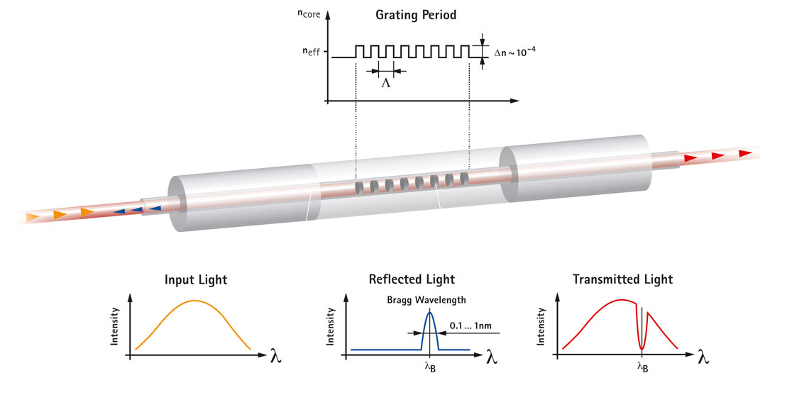
To create the actual strain sensor, the optical fiber is inscribed with a so-called Fiber Bragg Grating (FBG). This is basically a pattern of material interferences, which reflects the light differently from the rest of the fiber. For better understanding, you can visualize the fiber as a cylindrical length of transparent material, with several thin slices in it. When the light from the laser hits this pattern, certain wavelengths are reflected, while others pass through.
The material interferences – the 'slices' – are placed at certain intervals. When the fiber is stretched or compressed – and is therefore subjected to positive or negative strain – these intervals change. When the fiber is stretched, it lengthens, and the spaces get bigger and vice versa.
Not only does the reflected light take a little longer or shorter to travel back when the FBG is under strain, but the wavelength that is reflected also changes. In scientific terms, the FBG has a certain refractive index. The refractive index of a material describes how much light is bent or refracted when passing through the material. When the grating changes shape due to strain, its refractive index changes as well.
“One Fiber Bragg Grating as a whole is approximately 5 millimetres long, though the individual material interferences cannot be seen with the naked eye, only under a microscope,” explains Cristina Barbosa. Many Fiber Bragg Gratings can be inscribed in one long fiber – each working as an individual strain sensor.
When the optical fiber is applied to a material, it will be strained along with this material. The measured strain will in turn allow an analysis of the mechanical stress in the material, which is the aim of most strain measurements.
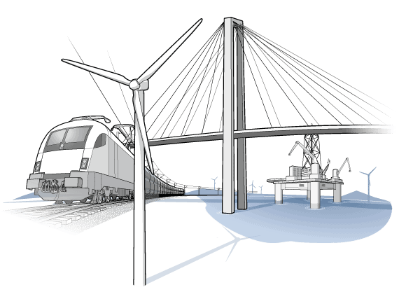
To give a practical example, when the fiber is applied to the girders of a long bridge, it is strained when there is stress in the girder elements. This can be, for example, due to the vibration of vehicles rushing by. When the structure settles or even develops weak points or cracks over the years, this becomes visible from the information about strain and thus mechanical stress acquired by the sensors – a useful early indication as to where maintenance is needed.
For measurements, the optical fiber needs to be connected to a so-called interrogator; it continuously sends out light in different wavelengths, one at a time, thus covering a wide spectrum. This is called “sweeping laser”. Light propagates through the fiber, is reflected at some point by a FBG and returns to the interrogator.
Thanks to the different periods of individual FBGs, it is possible to distinguish between the signals of different sensors. The rest of the light is refracted when reaching the end of the fiber so that it doesn’t interfere with the measurement. The actual strain and, in turn, the material stress can be deduced from the raw light signals, which return from the FBGs.
“While there are different methods of measuring strain with different kinds of fiber optic sensors, what they all have in common is that they rely in some way on the properties of light.”
- Cristina Barbosa, Product Manager HBK optical technology

Fiber Bragg Grating based optical fiber sensors are extremely susceptible to temperature. Obviously, the fiber − as any other material − expands when the temperature rises and contracts when the temperature drops. The refractive index changes as well. Without compensation, this would lead to the measurement of strain that has not been caused by material stress, but by temperature variations. There are several techniques for compensation, including:
Questions? Contact us!
We’ll be happy to help you.
“As part of the ITER project in France, our sensors need to cope with a huge temperature range starting from approximately −270°C up to 300°C while under the influence of intense electromagnetic fields. This is something that no electrical strain gauge could manage,” says Cristina Barbosa, describing one of her favourite applications for optical strain sensors.
Less exotic applications can be found, for example, in structural health or infrastructure monitoring. As a single fiber can accommodate many sensors, optical technology offers itself as a solution to huge projects such as tunnel or pipeline monitoring. Several fibers can be connected to a single optical interrogator, and cabling and installation costs are lower in comparison to traditional strain gauges.
Moreover, optical measurement technology is the first choice for all applications where the electricity needed for traditional strain gauges would be a problem, including environments with a lot of electromagnetic interference (for example, space) or where there’s a high danger of explosion (for example, oil refineries). In Cristina Barbosa’s words:
“Optical sensors are resistant to many harsh environments and not afraid of high voltage, radio frequencies or water. Therefore, they offer a lot of advantages for conventional measurements."
- Cristina Barbosa, Product Manager HBK optical technology

HBK's modular and scalable monitoring solutions, complemented by our competent support and service, save time and money, provide valuable insights, and help to increase the structure’s service life and safety.

This will bring together HBM, Brüel & Kjær, nCode, ReliaSoft, and Discom brands, helping you innovate faster for a cleaner, healthier, and more productive world.
This will bring together HBM, Brüel & Kjær, nCode, ReliaSoft, and Discom brands, helping you innovate faster for a cleaner, healthier, and more productive world.
This will bring together HBM, Brüel & Kjær, nCode, ReliaSoft, and Discom brands, helping you innovate faster for a cleaner, healthier, and more productive world.
This will bring together HBM, Brüel & Kjær, nCode, ReliaSoft, and Discom brands, helping you innovate faster for a cleaner, healthier, and more productive world.
This will bring together HBM, Brüel & Kjær, nCode, ReliaSoft, and Discom brands, helping you innovate faster for a cleaner, healthier, and more productive world.