Aug 29 2019
How to Prepare Material for a Gauge Installation
Read More
The fatigue life of electrical strain gauges is an often misunderstood topic. Some of our customers ask “What is the maximum fatigue life of strain gauges?” and “Which maximum amplitude of strain is allowed for how many cycles?” Materials are getting stronger (composite materials) and require endurable strain gauges for durability testing.
Electrical strain gauges are a well-proven sensor technology used for many tests in different branches such as static load tests, fatigue testing in component test, and full-scale tests. In this context, materials are improved and designed to be used at their limits to improve the weight-to-strength ratio and to fulfill the needs of new products in the future.
In these tests, materials need to be tested periodically in testing machines as components or as complete products or, in mobile tests, to simulate the stress situations to make sure that no failure will occur.
The unexpected failure of strain gauges during durability testing can result in considerable additional efforts and costs afterward. Therefore it is important to know how many load cycles a strain gauge can resist and which accuracy can be achieved.


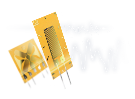
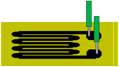
One of the limiting factors is the material used for electrical foil strain gauges. One of the main components of a foil gauge is the metal grid. The meander-shaped metal grid is intentionally deformed during loading to achieve a change in ohmic resistance. This ohmic resistance change can be detected as a voltage change in the Wheatstone bridge.
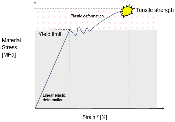
Frequently used metals for electrical strain gauges are constantan or CrNi (Modco). Constantan and Modco as metal materials have a similarity to other materials which are mostly known as construction materials such as steel and aluminum. Metals have a linear-elastic and a plastic region of deformation. The graphic below shows the behavior of steel in terms of stress and strain.
If a material is only stressed in the linear-elastic region the deformation of the material is reversible. Stressing a material above the yield limit brings the material to a point where it is plastically deformed. When a material reaches a specific stress value in this region, it will not return to its initial state when the external load is removed – the material is deformed irreversibly. This typical material behavior that is known from steel also exists in the materials used for foil strain gauges!
Unfortunately, the yield point/elastic limit cannot be extended to infinity and this is one of the reasons why the fatigue of electrical strain gauges is limited.
From this typical graph, the following can be derived: How long a foil strain gauge will survive a test depends on how it is stressed. Lower amplitudes definitely increase the fatigue life since the gauge is stressed in the linear-elastic region and the deformation of the material is reversible. Higher amplitudes are more critical and exceeding a specific limit means in the context of strain gauges that this can be done only once.
The following illustrations show how this behavior could look like in a mechanical test:
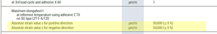
If a static load test is performed (1.) the strain gauge can be used in one direction (tension or compression) and exceed the yield limit. It still delivers a valid measured value in the plastic deformation zone. The maximum values for electrical strain gauges are specified as absolute strain in the strain gauge PDF catalog. The values for tension and compression are specified separately. For these tests, high strains between 1% and 10% are possible with HBM's foil strain gauges.
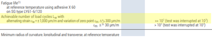
When the gauge is used in a dynamic load test (2.), i.e. with strain in alternating directions (tension and compression), exceeding the grid material's yield limit is not allowed. The maximum allowed values are also specified in the strain gauge catalog as the fatigue life. The fatique life implies the maximum permissible amplitude depending on the load cycles and the tolerance of the signal's zero-point drift. Strain gauges tested for fatigue life at HBM are tested in both directions (tension and compression).
One load cycle corresponds to 1x tension and 1 x compression at the specified amplitude.
Static strain means that the gauge can be loaded with the specified strain in one direction only once in its life time. When the specified limit is exceeded, the strain gauge is damaged with high probability.
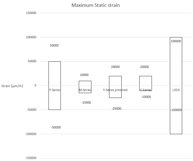
The following graph shows the maximum static strain that can be expected with different Y-Series gauges when they are loaded with +-5%, the M-series with up to 1% and our prewired gauges based on the Y-Series with up to +2,5/-2% strain.
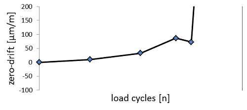
A foil strain gauge that is loaded multiple times in a fatigue test shows a strong correlation between the number of load cycles and the load amplitude. High strain amplitudes on the measurement grid material can create plastic deformation, which is recognized as a zero-point drift of the signal or the complete loss of the signal. In this case, the number of load cycles can be drastically reduced. The following graph shows that the fatigue life depends on several parameters. The correlation between load amplitude and load cycles is not linear.

The fatigue life of each foil strain gauge is specified in the strain gauge PDF catalog.
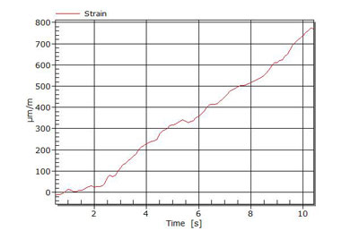
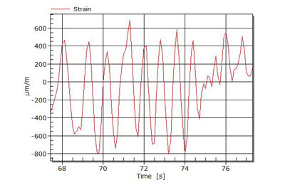
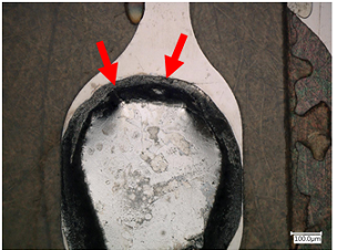
Cracks in the grid become visible by an interrupted sine signal. Small cracks open and close during cyclic loading and the signal is lost. So there is only partial electrical signal connection.
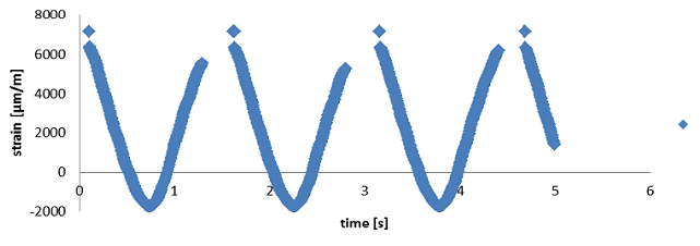
Also, visual cracks and irregularities in the strain gauge or the solder are showing that the gauge is damaged.
The following diagram shows the fatigue life of electrical strain gauges for load cycles between 1000 and 10,000,000 for Y- and M-Series gauges. The maximum achievable values depend on different factors such as the installation quality.
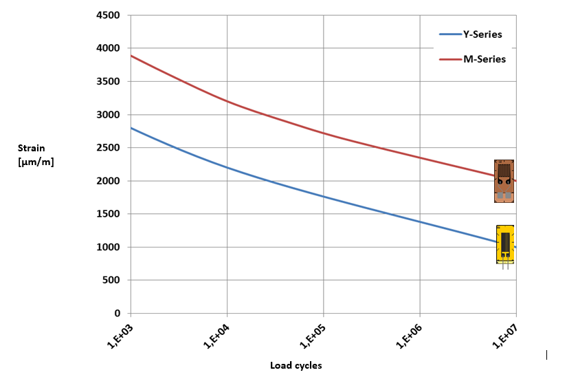
Measurements at higher amplitudes (>4000 µm/m) with electrical strain gauges show a further drop of allowable load cycles before the signal shows a significant zero-point shift. Strain tests at really high amplitudes show that the number of load cycles is massively reduced. Using, for example, M-Series gauges only for a swelling load test with +5200 µm/m this reduces the test to 1000 cycles. Testing at +7000µm/m reduces the test cycles to 100.
For testing higher load amplitudes at higher cycles, we also recommend to using optical strain gauges.
1. Minimize size the amount of solder material on the solder terminal.
Stiff regions of material are the most critical point for failure when applying static or dynamic load to them. A Professional soldering with as less as possible solder on solder terminal reduces the stiffness and increases the fatigue life.

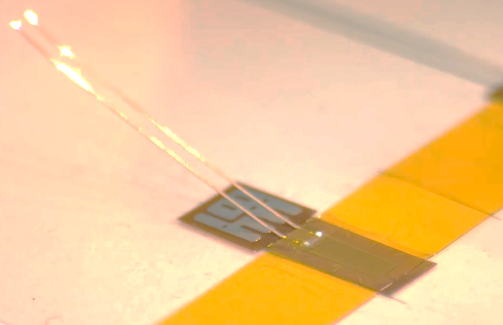
2. Solder the cable at 90° degrees to the strain direction.
Minimizing the contact surface on the solder terminal increases the fatigue life.
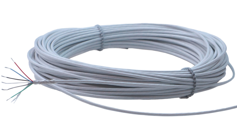
3. Use highly flexible wire material/leads.
Cables connected to the solder terminal are part of the mechanical system. Using stiff cables with large diameters increases the local stiffness. The stiffness can be reduced by use of flexible wires with thin diameters.
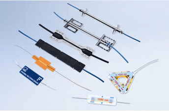
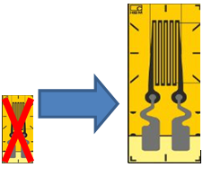
4. Use strain gauges with external solder terminals.
Using external solder terminals allows the use of strain gauges with leads. Strain gauges with leads offer the highest level of flexibility. There is no cumulation of solder material on the gauge itself. The solder is displaced to the solder terminal.
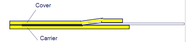
5. Avoid covering agents.
Covering agents should also be avoided if the maximum fatigue life is to be achieved. Since they interact with the strain gauge they could increase stress at specific points.

6. Use large measurement grids.
A larger grid area increases fatigue life (e.g. use 6mm grid instead of 3mm grids).
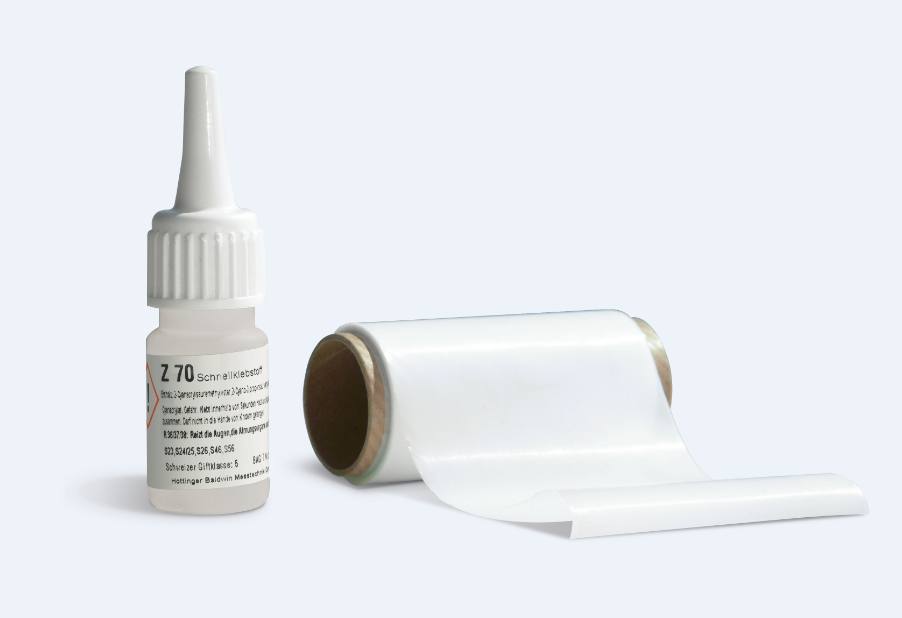
7. Ensure high quality of the bond.
Use thin adhesives such as EP310N.
8. Use gauges with encapsulation (standard for most HBM gauges).
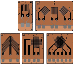
9. Use specific strain gauges for fatigue life.
The HBM M-Series has been developed especially for tests with high fatigue life materials. They have a highly resistant grid material (Modco) and a special carrier (phenolic resin). Additionally, they have an integrated strain-relief which decouples the solder tabs from the measurement grid.
HBM-M-Series
Legal Disclaimer: TECH NOTEs are designed to provide a quick overview. TECH NOTEs are continuously improved and so change frequently. HBM assumes no liability for the correctness and/or completeness of the descriptions. We reserve the right to make changes to the features and/or the descriptions at any time without prior notice.

This will bring together HBM, Brüel & Kjær, nCode, ReliaSoft, and Discom brands, helping you innovate faster for a cleaner, healthier, and more productive world.
This will bring together HBM, Brüel & Kjær, nCode, ReliaSoft, and Discom brands, helping you innovate faster for a cleaner, healthier, and more productive world.
This will bring together HBM, Brüel & Kjær, nCode, ReliaSoft, and Discom brands, helping you innovate faster for a cleaner, healthier, and more productive world.
This will bring together HBM, Brüel & Kjær, nCode, ReliaSoft, and Discom brands, helping you innovate faster for a cleaner, healthier, and more productive world.
This will bring together HBM, Brüel & Kjær, nCode, ReliaSoft, and Discom brands, helping you innovate faster for a cleaner, healthier, and more productive world.