arrow_back_ios

Main Menu

See All Software See All Instruments See All Transducers See All Vibration Testing Equipment See All Electroacoustics See All Acoustic End-of-Line Test Systems See All Academy See All Resource Center See All Applications See All Industries See All Services See All Support See All Our Business See All Our History See All Global Presence
arrow_back_ios

Main Menu

See All Analysis & Simulation Software See All DAQ Software See All Drivers & API See All Utility See All Vibration Control See All High Precision and Calibration Systems See All DAQ Systems See All S&V Hand-held Devices See All Industrial Electronics See All Power Analyzer See All S&V Signal Conditioner See All Acoustic Transducers See All Current and Voltage Sensors See All Displacement Sensors See All Force Sensors See All Load Cells See All Multi Component Sensors See All Pressure Sensors See All Strain Sensors See All Strain Gauges See All Temperature Sensors See All Tilt Sensors See All Torque Sensors See All Vibration See All Accessories for Vibration Testing Equipment See All Vibration Controllers See All Measurement Exciters See All Modal Exciters See All Power Amplifiers See All LDS Shaker Systems See All Test Solutions See All Actuators See All Combustion Engines See All Durability See All eDrive See All Production Testing Sensors See All Transmission & Gearboxes See All Turbo Charger See All Training Courses See All Acoustics See All Asset & Process Monitoring See All Custom Sensors See All Durability & Fatigue See All Electric Power Testing See All NVH See All Reliability See All Vibration See All Weighing See All Automotive & Ground Transportation See All Calibration See All Installation, Maintenance & Repair See All Support Brüel & Kjær See All Release Notes See All Compliance
arrow_back_ios

Main Menu

See All nCode - Durability and Fatigue Analysis See All ReliaSoft - Reliability Analysis and Management See All API See All Experimental Testing See All Electroacoustics See All Noise Source Identification See All Environmental Noise See All Sound Power and Sound Pressure See All Noise Certification See All Industrial Process Control See All Structural Health Monitoring See All Electrical Devices Testing See All Electrical Systems Testing See All Grid Testing See All High-Voltage Testing See All Vibration Testing with Electrodynamic Shakers See All Structural Dynamics See All Machine Analysis and Diagnostics See All Dynamic Weighing See All Vehicle Electrification See All Calibration Services for Transducers See All Calibration Services for Handheld Instruments See All Calibration Services for Instruments & DAQ See All On-Site Calibration See All Resources See All Software License Management
null

An Introduction to Optical Measurement Chains Based on Fiber Bragg Gratings (FBG)

This article aims to help system integrators and engineers choose the right components for multi-physics optical monitoring solutions. This is crucial, as all major structures – such as bridges, buildings, pipelines, and tunnels – are exposed to factors that cause strain and degradation. Without reliable and accurate monitoring of strain, temperature and other physical parameters, malfunctions and structural issues might not be detected, resulting in disasters.

In the following, we’ll discuss structural health monitoring (SHM) as a discipline, and we’ll show you how a typical optical Fiber Bragg Grating (FBG) based measurement chain – hosting several sensors in one optical fiber, interrogators, and PC software – can easily be designed.

null

Structural Health Monitoring – Preventing Failure instead of Repairing Damage

Large and expensive structures, such as tunnels, bridges, and pipelines, need regular, cost-effective monitoring of their structural integrity. This ensures safety and reliability.

Structural health monitoring (SHM) plays a critical role here [1], because it takes a proactive approach to maintenance and monitoring, rather than waiting for damage to happen and then repairing it. This proactive method can save money and prevent unplanned downtime of the structure.

But the need for reliable and accurate SHM installation in major infrastructure is often ignored for reasons such as cost, confusion over which sensors to use, and difficulty interpreting strain data. This becomes a problem when strain-induced structural damage happens. And it does happen regularly, since civil infrastructure is exposed to constant loads and environmental agents that cause wear and degradation over time.

For instance, bridges suffer from structural deterioration due to rising traffic demands, as well as climate changes and adverse weather conditions [2-3]. Poor construction methods, seismic activity, and nearby construction also play a part [4]. And without consistent monitoring, malfunctions and structural issues cannot be detected or predicted, resulting in disasters. In fact, in the United States, every bridge is required to undergo a visual inspection once every two years to help prevent such structural issues from cropping up [5].

But according to the ASCE 2017 Infrastructure Report Card, nearly 10% of bridges in the United States have some sort of structural problem, which makes them vulnerable [6]. And in Canada, almost one third of the approximately 75,000 highway bridges have structural deficiencies [7]. Failure to identify and deal with these structural deficiencies can result in high maintenance costs, shut down of local infrastructure, and −worst-case scenario – structural collapse and fatalities. As a result, there is a huge market for technology that helps to easily and cost-effectively monitor infrastructural wear and tear [8].

Use of Conventional Resistive Strain Sensors

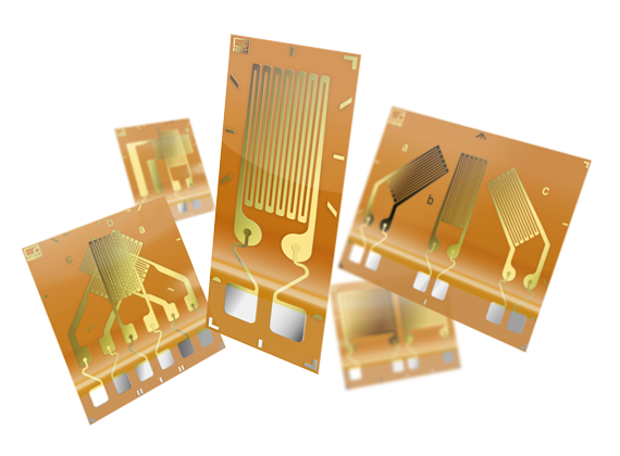
Since the 1940s, the resistive strain gauge has been the benchmark for structural strain monitoring [9]. But certain limits come along with resistive strain gauges and sometimes hinder easy and reliable measurement.

For example, the number of electrical cables needed can be a challenge. This is because long cables are costly, and lots of them can become difficult to manage when used in large scale structures with many measurement spots [10], despite the existence of technical solutions for measuring electrical strain over distances up to several hundred metres, and to both technologies [4].

null

Fiber Bragg Grating Technology: An Innovative Solution for Structural Health Monitoring

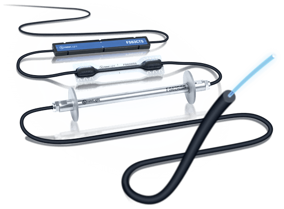
Optical sensors that are based on Fiber Bragg Grating (FBG) technology offer an attractive alternative to conventional electrical measurement chains.

This is because FBG technology has advantages such as multi sensors in a single optical fiber, overall lightweight passive design, and low attenuation, which allows long distance installation. This technology is also immune to electromagnetic interference (EMI), and sensors are more environmentally stable than electrical strain gauges (so they can withstand harsh conditions). They’re also competitively priced when it comes to a medium to high channel count and total cost of ownership [12, 13].

null

The benefits of FBG-based sensors:

  • Immune to electromagnetic noise interference (EMI) 
  • Low attenuation and can be installed over long distances 
  • Can have several sensors on the same line. This reduces cable length and complexity, and also simplifies installation which is more cost-effective 
  • Can withstand harsh conditions, minimizing the need for complex or expensive protection solutions 
  • Long-term signal stability (no drift) with an absolute zero reference (related measurements even if scattered in time)

FBG Technology Application Fields

Thanks to the fact that it can be easily used with your supplier’s software, and is also integrated into any individual PC, FBG technology has acquired a large market share over time. It’s now used in a wide range of sensing applications [13].

For instance, it’s used in different health monitoring applications in civil engineering, including road and railway infrastructure, but also in geo-structures, oil and gas, hull monitoring of vessels in the marine industry, aerospace structures, and automotive temperature validation.

More advantages of FBG technology:

  • Multiplexing many and even different sensors in a single fiber. All sensors will then come along with different wavelengths, reducing the amount of wiring needed for the sensing network.
  • Long-term signal stability and system durability, even with high vibration loads. Sensors are unlikely to fail on roadways and bridges where increasing traffic demands cause structural wear and tear.
  • Distance and cable length have minimal effect on measurement accuracy. Since FBG sensors experience low attenuation, the data is always reliable. And this is true even if the data acquisition system is several kilometres away from the furthest sensor.
  • Optical fibers are thinner and lightweight when compared to copper cable.
  • And, as mentioned above, FBG technology is not at all affected by electromagnetic interference (EMI) or radio frequency interference (RFI), which allows a sensor installation near safety critical parts such as railway overhead lines, and pantographs. 
  • These FBG sensors can also be used in highly explosive atmospheres and under other harsh conditions.
null

Optical Measurement Chains: The Complete Package For SHM

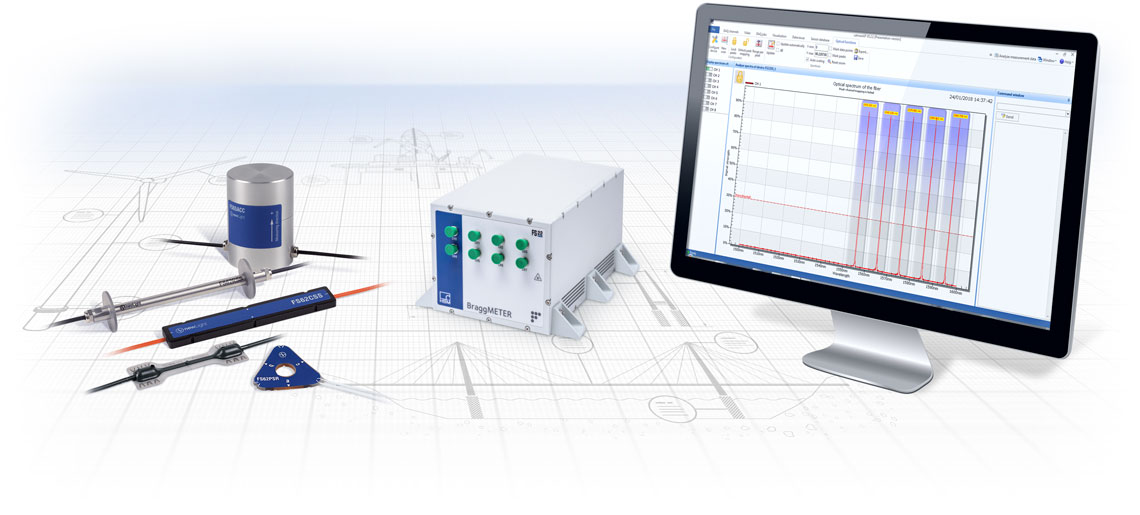
For a complete optical measurement chain, having the right sensor is only one third of the solution. You also need the right optical interrogator, and the right software in place to get overall reliable results.

And these three parts – sensor, interrogator, and software – complete your optical measurement chain.

In short, the sensor is what measures or ‘senses’ strain, temperature, acceleration, force or even tilt. The optical interrogator (the second component in the chain) is also known as a data acquisition system. It’s an optoelectronic instrument which ‘reads’ the FBG sensors. And the software is what allows you to view, record and analyse your measurement data.

   So what should you look for when choosing these components? 

1. Sensors

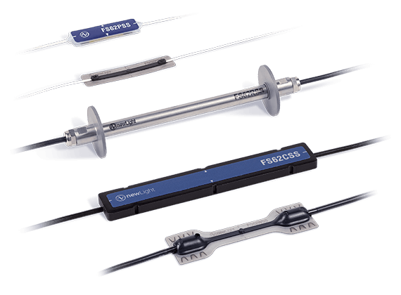
Here are some questions to ask and things to look for when choosing the right optical sensors based on FBG technology:

  • Where are the sensors going to be installed, and what is the preferred installation method? Sensors can be bolted, welded or glued depending on their design, which means that a preferred installation method might narrow down your options. For example, on a metallic structure the immediate choice goes to spot welding, but if the structure is an LNG tank (hazardous environment) we might have to switch to glued sensors on the surface.
  • What is the expected measurement range at each location? And what about fatigue resistance? Different sensors have different measurement and fatigue limits. The needed measurements might limit the number of possible sensors to select.
  • What is the expertise level of your installation team? Sensors, and arrays of sensors, can be delivered with plugs for straightforward installation without the need to use special tools or training, or without plugs for more flexibility. But this also needs a team ready for performing the splice connections on site.
  • What environment will the sensors be subjected to? Do they need to be dielectric? Do they need reinforced cables? Different sensors offer different protection levels on the sensor itself and on the cables.

2. Interrogators

Remember, your interrogator is designed to measure the values generated by your sensors. Here are a few things to look out for when choosing an interrogator:

  • What’s the needed sampling rate? One of the dictating factors of the model to use is the speed of acquisition of the device.
  • What is the needed absolute accuracy on wavelength measurement? On FBG sensors, the resolution and absolute accuracy can be determined, not only with the errors associated with the calibration procedures, but also with the resolution and accuracy of the interrogator in combination with the sensors’ sensitivity. Some instruments include an absolute NIST traceable reference that ensures higher accuracies on the determination of the wavelength of each FBG.
  • How many Fiber Bragg Gratings are there to measure? The available wavelength range of the interrogators together with the number of optical connectors correspond to the measurement capability of the system. The number of sensors that can be measured with each device depends on several factors: 
    • the wavelength range each sensor needs for the full measurement, in relation to the available wavelength range of the device
    • the optical losses on the sensor's line due to connections and cabling in relation to the device’s dynamic range
    • the device’s processing capability
  • Are you looking for an industrial device to operate continuously, or for a system to use in tests or during installation? Devices with batteries and built-in computers can be a better choice for measurements, which are short in time and separated in space. Other devices come in different form factors making them perfect for, for example, installation on 19″ racks.
  • Which level of software complexity does your system need? Not all software is compatible with all interrogator types.

3. Software

When choosing software, here are some important considerations:

  • How user-friendly is the software interface? What kind of visual feedback is necessary? Clunky and difficult-to-use software can cause you unnecessary headaches, and no software or drivers require an expert development team for operating the device.
  • How do you need the data? Is cloud storage and IoT streaming required? Can you put the data on a USB drive?
  • Are there more devices on the measurement system that need a synchronized measurement? More complex software allows the combination of more than one device (including different types of devices) and simpler software is limited to a single device
  • Is the software required for a unique application? A versatile software system can be equally reliable for mobile field use and lab bench testing.
  • Will the operator be familiar with English? Not all software options are available in different languages.

Conclusion

Optical sensors based on Fiber Bragg Grating technology have many advantages over conventional resistive strain gauges. Both sensor types can also complement each other in various applications, from civil infrastructure and aerospace, to lab testing and energy.

But to make use of these advantages, you need to choose the right sensors, interrogators and software for your optical measurement chain. Our hope is that this brief primer can help engineers and system integrators make the right decisions when it comes to accurate and reliable strain measurements.

Get to know more about HBM..

null

Curious? Sign up!

Be the first to learn more about the new MXFS optical interrogator for structural health monitoring.

This text placeholder needs to be substituted with a form component later. Component id: 390002

About HBM Products and Services

Engineers worldwide rely on accurate and reliable measurement data acquired using sensors, interrogators, and software from HBM.

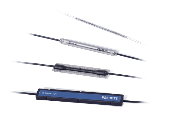
For instance, our optical sensors from the newLight product line – based on FBG technology – allow large strain measurement ranges with long-term stability. These sensors are the best choice for SHM (Structural Health Monitoring) due to their fast and easy installation and suitability for harsh environments.

On the optical interrogator side, HBM instruments provide high-resolution static and dynamic measurements 24/7. For instance, we have developed the brand new MXFS model for structural health monitoring. Along with our optical sensors, this interrogator helps you ensure a seamless measurement chain.

Lastly, HBM’s software is the final link in your optical measurement chain. Our data acquisition software (such as catman) manages millions of datasets and helps you get your results quickly.

One key advantage of HBM products is the possibility to mix and match sensors, interrogators, and software to suit your needs. We offer a complete product portfolio for SHM, giving you everything you need for accurate and reliable strain measurements. Table 1 below shows the compatibility of HBM interrogators and software. For more information on these products and on how to choose the right components for your optical measurement chain, please contact us.

  BraggMONITOR catman
FS22SI  YES YES
FS22DI YES YES
FS42PI YES NO
MXFS NO YES

References

[1] Engineering.com, “Italy’s Morandi Bridge Collapse—What Do We Know?”, 2018. 
https://new.engineering.com/story/italys-morandi-bridge-collapsewhat-do-we-know

[2] Alampalli, S.,  Ettouney, M., “Role of Structural Health Monitoring In Bridge Security”. Bridge Structures 4(3,4), 143-154, 2008. 
https://www.researchgate.net/publication/245494458_Role_of_structural_health_monitoring_in_bridge_security

[3] E.Cheilakou et al. “Strain Monitoring System For Steel And Concrete Structures” Procedia Structural Integrity 10, 25-32, 2018. 
https://www.sciencedirect.com/science/article/pii/S2452321618300532

[4] Cristina Barbosa “Optical Fiber Sensors vs. Conventional Electrical Strain Gauges for Infrastructure Monitoring Applications”, HBM.

[5] U.S. Department of Transportation, Federal Highway Administration, “State of the Practice and Art for Structural Health Monitoring of Bridge Substructures” (No. FHWA-HRT-09-040)], 2014. 
https://www.fhwa.dot.gov/publications/research/infrastructure/structures/bridge/09040/

[6] American Society of Civil Engineers, 2017 Infrastructure Report Card, 2017. 
https://www.infrastructurereportcard.org/cat-item/bridges/

[7] National Research Council Canada (NRCC), Construction Innovation, “Critical Concrete Infrastructure: Extending The Life of Canada’s Bridge Network”. 
https://www.nrc-cnrc.gc.ca/ci-ic/en/article/v18n1-5/

[8] Gastineau, A., Johnson, T., & Schult A. “Bridge Health Monitoring and Inspections–A Survey of Methods”, Minnesota Department of Transportation, 2009. 
https://www.researchgate.net/publication/282912591_Bridge_Health_Monitoring_and_Inspection_-_A_Survey_of_Methods

[9] The Strain Gauge User’s Handbook, Chapman and Hall, 1992.   
https://books.google.co.uk/books?id=YrNr00vhF_gC&printsec=frontcover&dq=resistive+strain+gauges&hl=en&sa=X&ved=0ahUKEwjBxdDgxMvjAhVJTsAKHWQlAroQ6AEIKjAA#v=onepage&q=resistive%20strain%20gauges&f=false

[10] Ramakrishnan et al. “Overview of Fiber Optic Sensor Technologies for Strain/Temperature Sensing Applications in Composite Materials”, Sensors, 16 (1), 99, 2016.  
https://doi.org/10.3390/s16010099

[11] Vishay Precision Group, “Noise Control in Strain Gage Measurements” Tech Note TN-501-2. 

[12] Sabri et al.“Fiber Optic Sensors: Short Review and Applications”, DOI: 10.1007/978-981-287-128-2_19, 2015. 
https://www.researchgate.net/publication/278680033_Fiber_Optic_Sensors_Short_Review_and_Applications

[13] Campanella et al., “Fibre Bragg Grating Based Strain Sensors: Review of Technology and Applications”, Sensors, 18(9):3115, 2018. 
https://www.researchgate.net/publication/327710750_Fibre_Bragg_Grating_Based_Strain_Sensors_Review_of_Technology_and_Applications 

[14] Peters et al. “Fiber Optic Sensors For Assessing And Monitoring Civil Infrastructures”, Sensor Technologies for Civil Infrastructures, 1, 121-158, 2014. 
https://doi.org/10.1533/9780857099136.121

[15] Ma et al. “Fiber Bragg Gratings Sensors for Aircraft Wing Shape Measurement: Recent Applications and Technical Analysis”, Sensors (Basel), 19(1): 55, 2019. 
https://www.ncbi.nlm.nih.gov/pmc/articles/PMC6339136/

Continue Reading

No more result to load