Traditional power analyzers were designed for measuring power lines at 50 and 60 Hz and use a PLL technology that takes time to settle onto a fixed frequency. This settling time is often in the order of seconds. Once the PLL has settled on a waveform, it determines the frequency and will use the time period for RMS and power measurements. If the frequency is constantly changing, the PLL will not settle and it will make its measurements on an arbitrary time period. This often results in impossible results such as efficiencies greater than 100%.
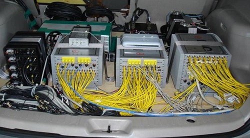
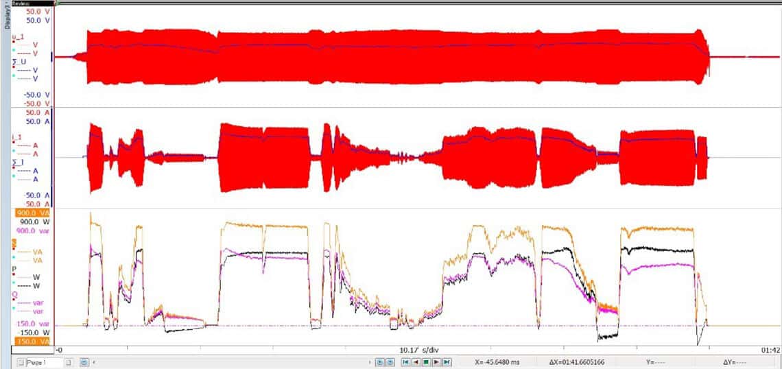
Traditional power measurement systems also typically lack visual feedback or recorded data, which significantly limits the traceability of the measurements. During an in-vehicle powertrain measurement, test engineers typically want to measure a certain set of powers, voltages, or currents and need visual feedback to indicate when they have achieved their given setpoint.
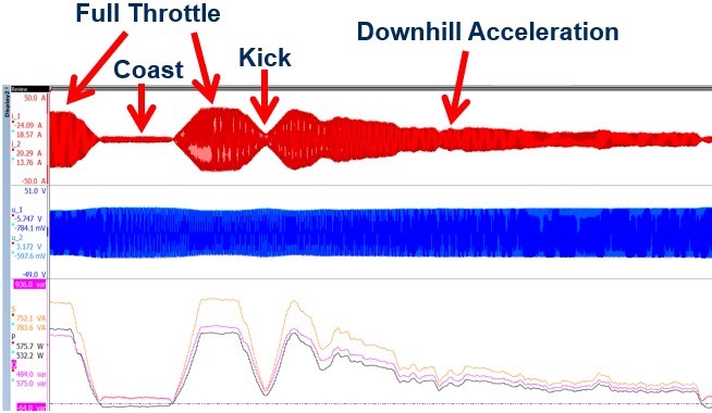
Without feedback, it is difficult to know if the vehicle has achieved a certain loading point and for how long it has operated at that point. Control engineers will also use this feedback to monitor the Id and Iq control variables. Visual feedback gives the engineer insight into how the vehicle responds to different disturbances, or if they have met their set points. The use of visual feedback is vital for competitor vehicle benchmarking where control strategy or powertrain performance are largely unknown.
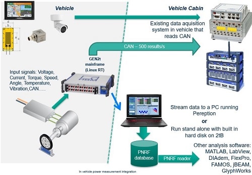
Traditional power measurement systems also lack a method of correlation and feedback to external systems. This is necessary to correlate their power signals to environmental data often collected by existing data acquisition systems.
GPS, video, temperature, and the vehicle status give an engineer significantly more insight into what was happening during the test. Hard braking, swerving to miss an obstacle, or harsh traffic conditions may affect a vehicle output or demonstrate a bug in the vehicle control. Without GPS or video, engineers rely on the driver’s memory to recall these events. A proper test run would need to incorporate external test conditions to achieve full transparency of the test results.
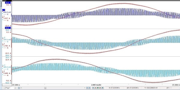
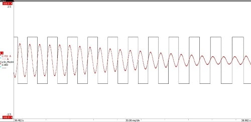
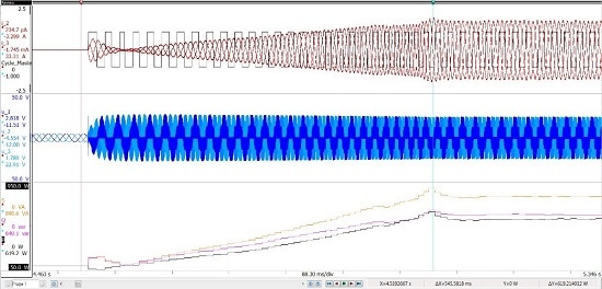
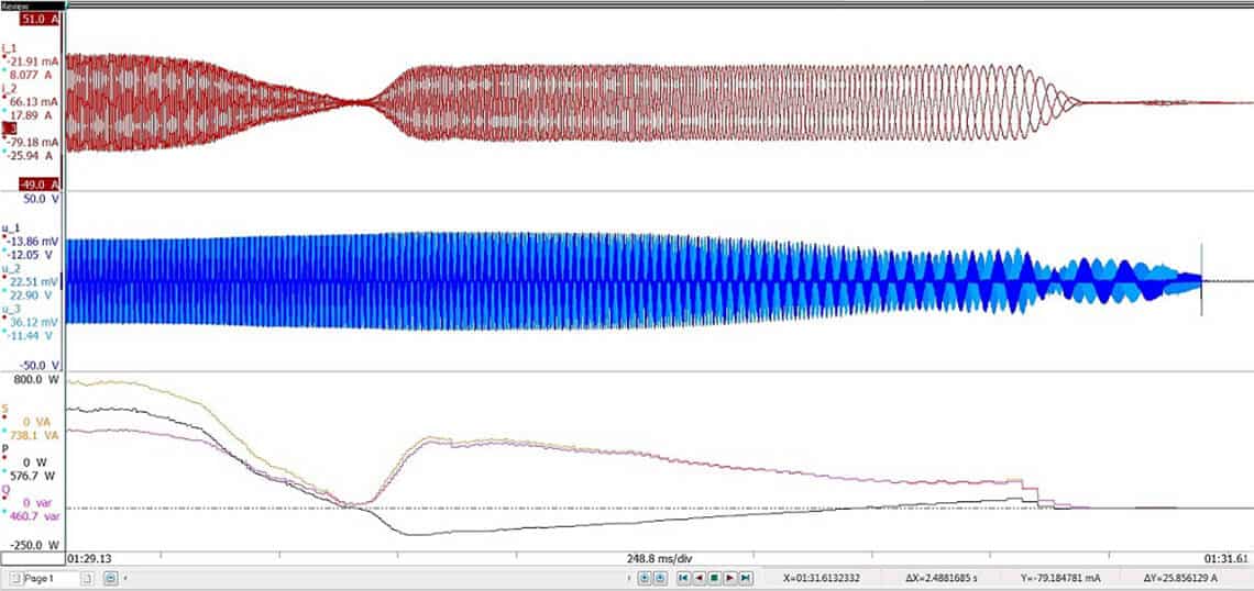
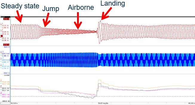
More traditional mobile DAQ systems were not intended for high-frequency and high-voltage signals generated by inverters. Mobile DAQ systems have sample rates that max out around 100 kS/s, which is more than enough for structural or frequency data but does not provide enough bandwidth to get a good power accuracy from a PWM inverter. These inverters, which turn on and off at high voltages, and at frequencies greater than 20 kHz, , require a much higher sample rate to accurately measure RMS voltages and currents. An example set of high-frequency inverter signals is shown in Fig. 4.