Aug 29 2019
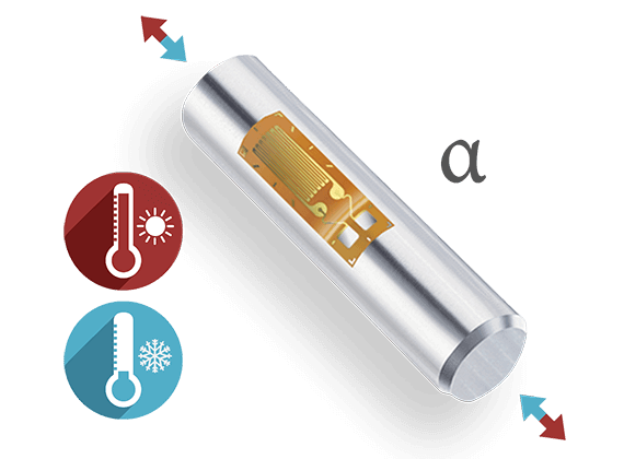
Temperature Compensation of Strain Gauges
Read More
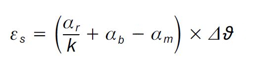
The following applies here:
εs Apparent strain of the strain gauge
αr Temperature coefficient of the electrical resistance
αb Thermal expansion coefficient of the measurement object
αm Thermal expansion coefficient of the measuring grid material
k K factor of the strain gauge
Δϑ Temperature difference that triggers the apparent strain
On all of their strain gage packs, HBM shows the apparent strain as a function of temperature in a chart and also as a polynomial. Of course, these data only ever give useful results if the thermal coefficient of linear expansion of the material to be tested matches the data on the strain gage pack.
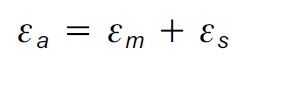
The following then applies:
But the apparent strain can also be used perfectly well for measurement purposes, if the coefficient of thermal expansion αm is to be determined. In this situation, the following formula can be used:
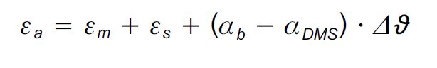
Transposed, this produces:
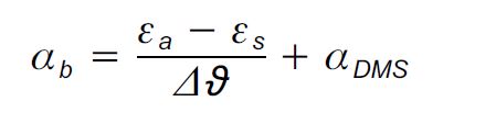
εa Strain indicated at the amplifier
εm The strain triggered by the mechanical load
αDMS Thermal coefficient of linear expansion as per the strain gauge pack
In a practical test, four HBM strain gauges of the LG11-6/350 type, adapted to steel (α=10.8 10-6/K), were installed on an aluminum workpiece. A four-wire circuit was used to eliminate cable influences. According to the data supplied by the manufacturer for the material, α=23.00 *10-6/K for T= 0 … 100°C.
| ϑ (°C) | εa(*10-6) | εs(*10-6) | εa-εs(*10-6) | αb(*10-6)/K |
| -10 | -396.9 | -38.0 | -358.9 | |
| 0 | -254.4 | -16.9 | -237.5 | 22.9 |
| 10 | -122.5 | -5.0 | -117.5 | 22.8 |
| 20 | 0 | -1.1 | 1.1 | 22.7 |
| 30 | 118.8 | -3.9 | 122.7 | 23.0 |
| 40 | 232.4 | -12.2 | 244.6 | 23.0 |
| 50 | 344.3 | -24.8 | 369.1 | 23.2 |
| 60 | 453.3 | -40.3 | 493.6 | 23.3 |
| 70 | 562.1 | -57.7 | 619.8 | 23.4 |
| 80 | 671.6 | -75.6 | 747.2 | 23.5 |
| 90 | 781.8 | -92.7 | 874.5 | 23.5 |
| 100 | 894.1 | -107.9 | 1002.0 | 23.5 |
| 110 | 1010.5 | -119.9 | 1130.3 | 23.6 |
| 120 | 1132.3 | -127.4 | 1259.8 | 23.7 |
Tab. 1 Measurement results for a strain gauge adapted for ferrit. steel, installed on aluminum
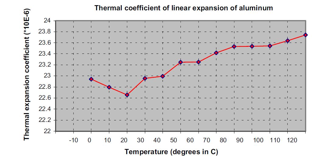
If you calculate αm for the specified interval, you obtain 23.19 *10-6/K, which corresponds to a deviation from the theoretical value of 0.19 *10-6/K (0.84%).
To run the experiment, it is first necessary to install several strain gauges on the object under investigation (to attain experimental reliability). The sample must be flat in the direction of the measuring grid.
In the next step, the strains are determined subject to the temperature. Care must be taken to ensure that thermal equilibrium is established.
First εa-εs is calculated. To determine the thermal coefficient of linear expansion, you subtract the two calculated values (εa-εs ) from each other and divide this by the corresponding temperature interval. The coefficient of thermal expansion αDMS as per the pack data must then be added to this.
Example: In the interval from 20 to 40 degrees, the coefficient of thermal expansion is calculated as follows (using calculation shown in Formula 4):

During this measurement, the strain gauge creep is an undesirable effect. So in the interest of maximum accuracy, it is advisable to use HBM series K strain gauges, which have three different creep adjustments as standard and of these, use the strain gauge with the greatest end loop length.
Also, when the measuring temperatures are over 60 °C, it is advisable to use hot curing adhesives for installation.
Note: Subject to modifications. All product descriptions are for general information only. They are not to be understood as a guarantee of quality or durability.

This will bring together HBM, Brüel & Kjær, nCode, ReliaSoft, and Discom brands, helping you innovate faster for a cleaner, healthier, and more productive world.
This will bring together HBM, Brüel & Kjær, nCode, ReliaSoft, and Discom brands, helping you innovate faster for a cleaner, healthier, and more productive world.
This will bring together HBM, Brüel & Kjær, nCode, ReliaSoft, and Discom brands, helping you innovate faster for a cleaner, healthier, and more productive world.
This will bring together HBM, Brüel & Kjær, nCode, ReliaSoft, and Discom brands, helping you innovate faster for a cleaner, healthier, and more productive world.
This will bring together HBM, Brüel & Kjær, nCode, ReliaSoft, and Discom brands, helping you innovate faster for a cleaner, healthier, and more productive world.