Calculating electrical power using QuantumX and catman Calculating electrical power using QuantumX and catman | HBM

Precisely Calculating Electrical Power using a QuantumX and catman Software

In many applications acquiring electrical signals and then subsequently calculating power and analyzing signals in the time domain and frequency range is a topic of growing importance. This article provides practical tips on how to carry out the necessary steps to complete these tasks using an HBM QuantumX MX403B and HBM catman software.

Electrical actuators are used in an increasing number of applications such as in elevators, escalators or as car components. Actuators (e.g. drives or valves) are rapidly replacing hydraulic systems used for calculating electrical power up to now. Hence, acquiring "electrical quantities," such as voltage and current is becoming increasingly important.

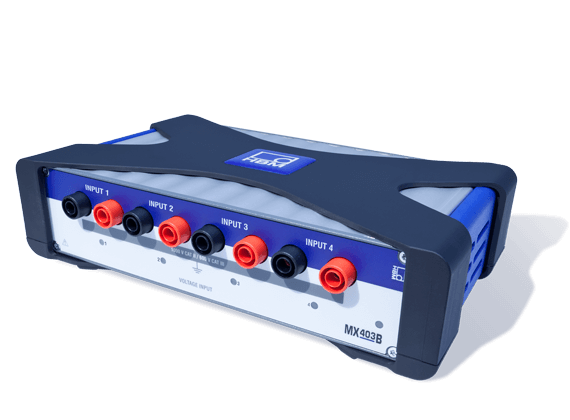
The QuantumX data acquisition system allows for acquisition of both electrical quantities and typical physical quantities, and the QuantumX MX403B 4-channel measurement module has been developed specifically for precise acquisition of voltages. QuantumX MX403B module also enables small differential voltages at a high electrical potential to be measured.

Note: Measurement of hazardous voltages may only be carried out by trained personnel. Measurement categories as defined in IEC 61010 play an important role in helping you choose the right measuring equipment. Please also refer to the safety instructions in the MX403B operating manual.

QuantumX MX403B Data Acquisition System

The QuantumX MX403B module has four isolated differential measurement channels for direct measurement of voltages up to 1,000 V DC or 1,000 Vrms AC. The measuring ranges of 10, 100 and 1,000 V can be freely parameterized. The ranges can enable acquisition of high voltages against reference ground as well as measurement of small differential voltages at a high potential against reference ground. Every channel is equipped with analog anti-aliasing filters, 24-bit AD converters and digital filters, and each can be individually parameterized.

QuantumX modules can be physically distributed and connected within close optical range of the measuring point (optical Ethernet or optical FireWire) to ensure maximum reliability between the measuring point and the PC.

The module permits sample rates up to 100 kS/s per channel and bandwidths up to 40 kHz and can be seamlessly incorporated into the existing QuantumX data acquisition system. The QuantumX solution allows acquisition of all physical measurands from the mechanical, electrical and thermal worlds, completely synchronously. It calculates the signals, establishing itself as a comprehensive complete solution and a valuable tool in research and development.

Measuring Voltage with QuantumX MX403B

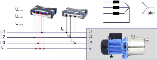
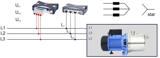
Of course, when measuring voltages, it is essential to know at what potential/reference point the measurement is taken. The MX403B module is perfectly suited for measurement, analysis and testing tasks and measures direct voltages on or in energy storage devices or alternating voltages in 1-phase or 3-phase operation in compliance with measurement categories CAT II and III. In 3-phase operation, we distinguish between 3- and 4-wire three-phase current systems, depending on whether or not a neutral is available. This also determines the measurement circuits for determining electrical power.

Three-phase current systems often use the star or Y configuration. The three windings (L1, L2, L3) are connected to a common point in the motor. This "common star point" was led out into the junction box and used for switching from star to delta when starting up a motor in the past.

With the increasing prevalence of electronic converters this is rapidly changing. With three phases, power is added geometrically from the individual power values; since the current is measured in each phase separately, it needs to be multiplied by the voltage of each phase. Only in rare cases can the phase voltage be tapped directly. Therefore, one of the following methods is used: 

  • Calculation of star voltages U1N, U2N, U3N from delta voltages U12, U23, U31.This is inaccurate, however, it is applied in practice
  • Generation of a reference point outside of the motor via an R or RC network (virtual star). This is more accurate and well suited for balanced loads. However, assuming that the motor is perfectly balanced both in terms of design and behavior, a SINGLE power channel would be sufficient. This needs to be analyzed.

When designing electric motors, special consideration is given to generating balanced loads, i.e. the neutral does not carry current. If the star is not led out (no neutral and thus three-wire circuit), an "external virtual star" can be configured. The G068-2 adapter provided by HBM can be used for this purpose. The G068-2 comprises three RC networks. The box precisely fits onto the MX403B's banana sockets, however, it limits the range to AC 600 V.

Acquiring Current with QuantumX MX403B

Electric current can be measured based on different principles. While a zero flux converter, shunt or Hall sensor converter allow for precise, phase-synchronous measurements of small currents, current probes are particularly suitable for quick current measurements in 1-phase and 3-phase operation. Current clamps enable a wide range of electrically isolated measurements of alternating currents (often also direct currents) without the current carrying line having to be opened. Furthermore, current clamps are inexpensive and allow for power analysis in applications with less stringent accuracy requirements. Different designs of current probes are available for different purposes (inductive, Hall effect).

The inductive measurement principle results in aphase delay in thecurrent transformer (skewing)between the current clamp's real current and its output voltage, which needs to be compensated for prior to calculating the power. This involves correspondingly delaying the measured voltage. With some current clamps, the phase angle error varies according to the frequency and over the measuring range, which, of course, impacts on the power calculation! Depending on the measuring range, 3 to 10° can occur at reference conditions. Please note: a perfect sinusoidal voltage, 45…60 Hz, 23° C ambient temperature and 50% relative humidity are used as reference in most cases. Every deviation from this reference can and will impact on the accuracy of the current measurement and thus of the power calculation. Therefore, selecting the right current clamp is of paramount importance. For this reason, HBM directly offers current clamps.

The phase shift needs to be compensated for to enable the power calculation to be performed correctly. The easiest way to compensate for the phase shift and thus determine power is to delay the measured voltage correspondingly. This process is described in more detail below. Now that both electrical quantities have been discussed, we can consider the software required for calculating electrical power.
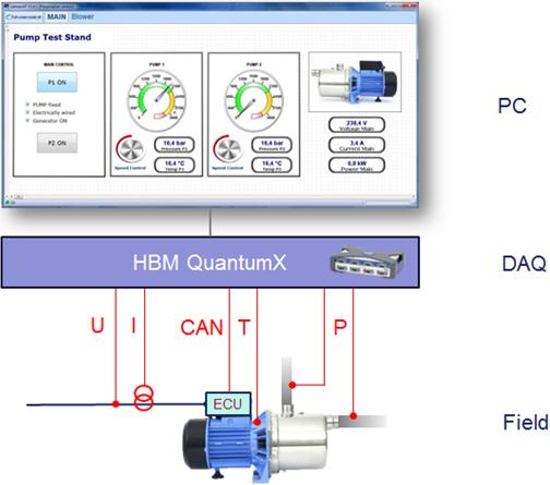
catman Data Acquisition Software

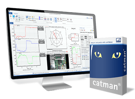
HBMatman DAQ software is ideally suited for measurement acquisitions in the following steps in your calculation:

  • Parameterization of channels (storage of channel settings for the sensors used, e.g. current probes)
  • Optional phase compensation when using current probes
  • Calculation of signals for effective, apparent and reactive power as well as other factors 
  • Visualization of raw values and calculated values in individual displays
  • Data storage in the desired data format
  • Analyses during ongoing measurement
  • Post-process analysis and reporting

In addition to measurement acquisition, catman software also offers an integrated mathematics library. The mathematical functions include simple algebraic calculations, statistical and spectral analyses, and calculation of electrical power and efficiency. The software can also calculate root-mean-squared (RMS) value of input quantities.

Step-by Step Measurement, Online Calculation and Analysis Using catman

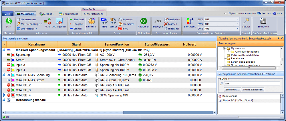
sensor database can help you to parameterize the measurement channels. If the correct signal description cannot be found in the sensor database, you can check the relevant data sheet. Using the sensor data sheet makes it easier to set the parameters of each individual channel later and it makes the process reproducible at any time.

Phase-Sychronous Analysis of Signals

Acquisition is synchronous for all channels of a QuantumX data acquisition system. It offers many possible sensor and transducer technologies to convert physical quantities-such as voltage, current, torque, rotational speed, temperature, acceleration, vibration, noise, and bus signals for control device communication into digital signals.

In our example, the current is measured by a shunt. Shunts are often used to measure alternating and direct current. The structure of shunts is purely resistive, therefore, shunts have no phase delay.

What to Do by a Phase Delay Between Current and Voltage?

Due to their inductive measuring core, current probes have a phase delay. This means the phase of the converter's output signal is delayed relative to the current phase. If the phase delay of the converter is not known, it can easily be gaged by measuring the current and voltage on a resistive consumer (for example, a filament bulb) and correcting it using catman EASY software. The measured voltage can be delayed correspondingly. For example, current probes can be connected to the QuantumX MX403B module using a banana-to-Bayonet-Neill-Concelman (BNC) adapter.

The current probe can also be connected via another measuring amplifier in a group such as a BNC-to-SubHD adapter on the MX840A universal amplifier. This amplifier is also able to record the following variables: torque, rotational speed, temperature, acceleration, vibration and CAN bus signals.

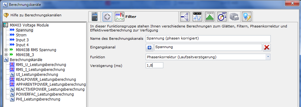
On the right side is an example of the phase correction in catman: Computing channels > Filter > Phase correction function

Online Power Calculation with catman

Power calculation considers low-frequency harmonic signals only (< 100 Hz). The process does not involve any complex integration algorithms. Common standard formulas are used. Power calculation in catman Easy incorporates a window-based process. The accuracy of the power calculation thus depends on the fundamental frequency of the signal and the width selected for the window. The calculated power will exhibit a slight residual ripple, even in a static system.

For example: 50 Hz fundamental oscillation -> 20 ms per period -> 100 ms window -> 5 periods on average.

Complete calculation of all quantities in catman EASY includes the RMS value and also the mean value (MEAN) over a time window. Neither one is formed in a straight forward averaging process with n values, as in the QuantumX MX403B module, as an example. (This would require a buffer for n values, so maximum time window would be limited!) Instead, the process is a one-step iteration with no buffer. The formulas are as follows:

  • RMS (n) = sqrt((1-a)*measured value(n)*measured value(n) + a * RMS(n-1))
  • MEAN (n) =  (1-a)*measured value(n) + a * MEAN(n-1))
  • a = exp(-1/(sampling rate * time window)).

The process is faster, requires practically no buffer, and can therefore implement time windows of any size. The result agrees closely with the values calculated on-board a QuantumX MX410B or  QuantumX MX403B amplifier. RMS and MEAN can also be filtered for smoothing. The other computing channels are calculated as follows:

  • REALPOWER = MEAN(U * I)
  • APPARENTPOWER = RMS(U) * RMS(I)
  • REACTIVEPOWER = sqrt(APPARENTPOWER*APPARENTPOWER – REALPOWER*REALPOWER)
  • POWERFACTOR = REALPOWER/APPARENTPOWER
  • PHI = acos(POWERFACTOR) * 57.29 to go from rad to °

Screenshot Gallery

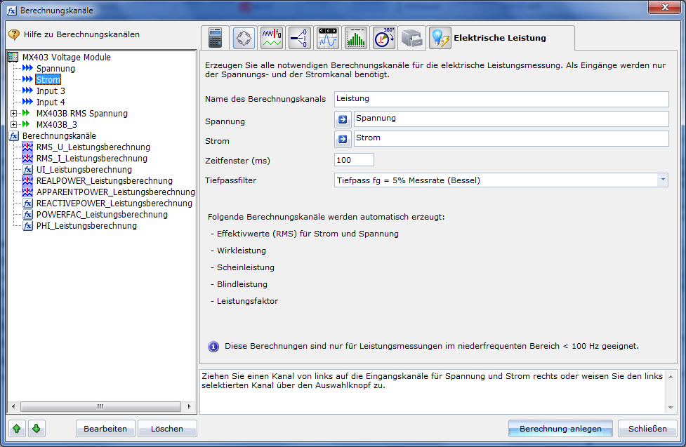
The process of parameterizing the power calculation.

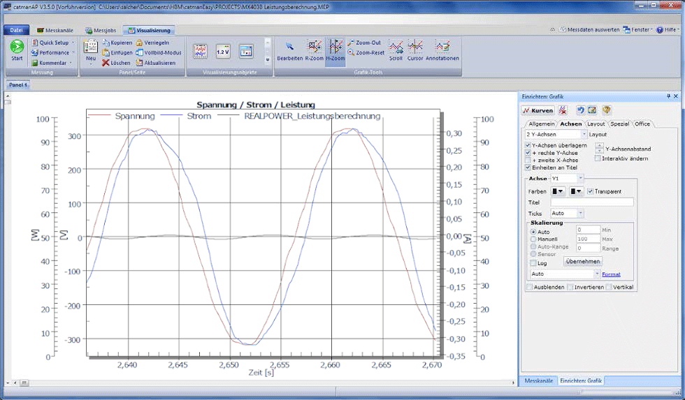
Next, you perform a measurement with the quantities you have just obtained. In the example, the measurement object is a 60-watt filament bulb. The graph can simply be exported to a measurement report in Microsoft Word with Text Markers (in the Office tab).

In comparison, another graph shows a measurement of inductive loads. In this case, the measurement object is a 50-watt soldering iron.

Data Analysis of Recorded Measurement Data with catman

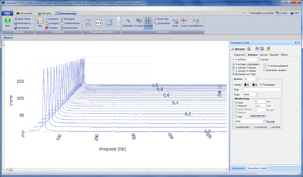
Subsequently, a signal analysis in the frequency range is performed. A signal analysis of this type is based on the Fast Fourier Transform (FFT). It facilitates the transition from time signals to the frequency range. Using catmanEasy measurement software, you can visualize and analyze the frequency distribution of one or multiple signals. Below, the number of measured values used for calculating the amplitude spectrum is a required parameter.

Frequency analysis in the post-process mode uses the FFT to calculate a spectrum (an amplitude, phase or power spectrum). Displaying multiple spectra over time is especially important in dynamic operation. A "waterfall diagram" can successively display amplitude spectra tiered in three dimensions. The view can be freely rotated in all directions. Activate 'Generate Frequency Data Set' to have the frequency channel available for export.