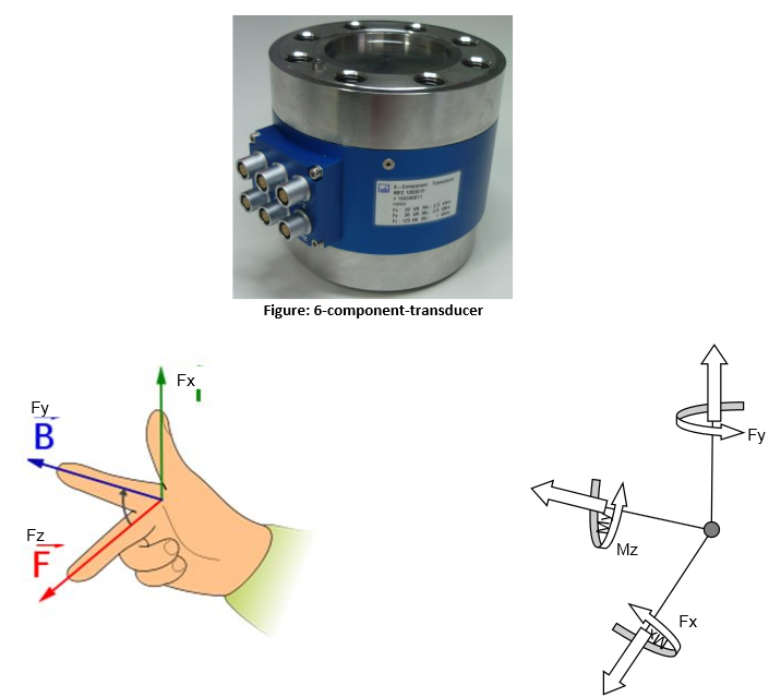
More and more test engineers in Aerospace, Machinery and Automotive request custom made sensors from HBM. These types of sensors measure force and torque in the requested degree of freedom and are called multi component or multi axis transducer. The picture below shows a6-component-transducer.
PMX Matrix Compensation
This Technote explains how to compensate the cross talk of measured values by using matrix compensation. In this example a multicomponent transducer is used, which is able to measure force and torque values within all degrees of freedom.
Required Material
In order to realize the example, the following components are necessary:
- 1 x PMX System (incl. supply)
- 1 x Transducer (6-component-transducer)
- 1 x calibration protocol (coefficient-compensation-matrix)
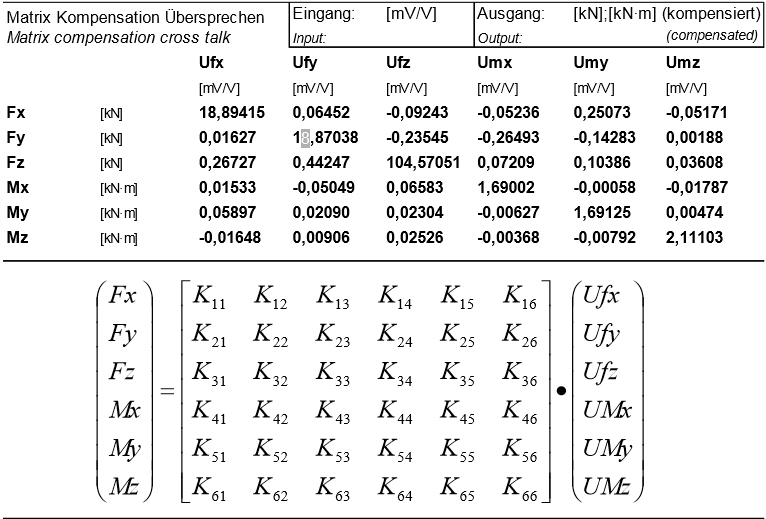
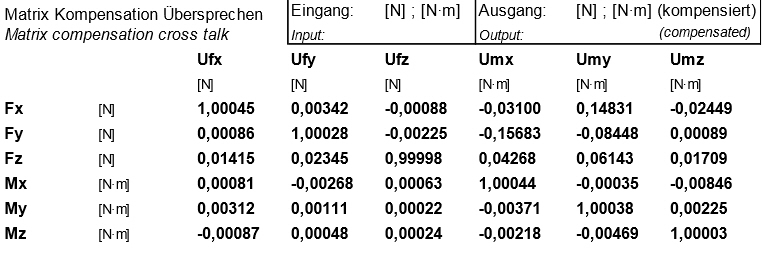
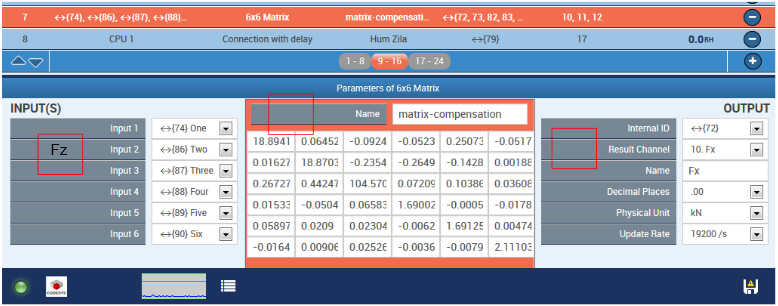
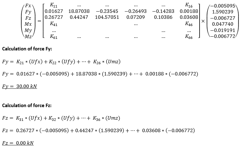
HBM delivers together with the sensor itself a so called compensation matrix. The matrix itself shows the cross-talk or cross influence between components, i.e. Fx to Fy and so on. Ufx, Ufy and so forth are the raw signals measured in mV/V; K11, K12 ... are the coefficients.
Multiplication of the measured quantities with the matrix results in fully compensated force and torque values in X, Y and Z direction. Fx, Fy ... are compensated real outputs in N or kN according the protocol delivered. A matrix example is displayed below.
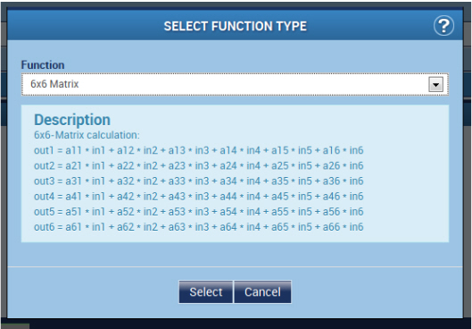
As shown in the figure above, the sensor signals (Ufx-UMz) are multiplied with the coefficient-matrix and eventually summed up for every line. The results are the values for force and torque (Fx-Mz).The results can be outputted directly on the device or again get parameterized as isochronous to be available in the system.
Output of Results
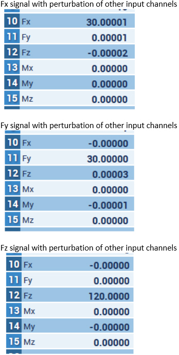
The outputs are mapped on internal channels in this example to be able to show the results in the web browser. The figures below show the results of different measurements where perturbation is eliminated by the matrix.
Legal Disclaimer
These examples are simply for the purpose of illustration. They cannot be used as the basis for any warranty or liability claims.
