Simulating an incremental-encoder Simulating an incremental-encoder | HBM

PMX: Simulation of an incremental rotary encoder

Some functions blocks enable a digital incremental rotary encoder with two tracks and zero index to be simulated. A displacement or angular value is used as input signal.

Introduction

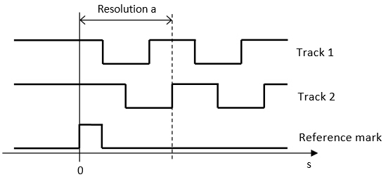
The following digital signals are derived from a signal s:

For example, s is a displacement in mm or an angle in degrees. Resolution a is exactly one period of an output signal; it has the same unit as s.

The method applied does not support negative s values.

The signals are output via the PX878 plug-in card's digital outputs. The electric properties limit the maximum frequency to approximately 1 kHz.
Procedure

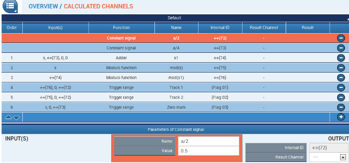
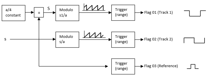
At first, ¼ of resolution a is added to s to obtain the desired phase shift between Track 1 and Track 2.The periodicity is generated by modulo blocks ( = remainder of division s/a). The signals generated in this way have period a and the range of values 0 ... <a.

Finally, the trigger blocks generate digital signals (Flags) through comparison with a/2.

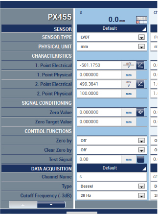
In this example, a displacement encoder 0..100 mm provides s:

The resolution is a=1 mm. Constant signals provide a/2 and a/4:

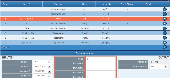
Phase shift: s1 = s + a/4

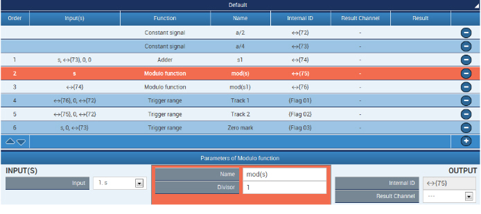
The modulo blocks provide the periodic signals for "Track 1" and "Track 2".The divisor is resolution a, in this case 1 mm.

Trigger blocks convert the periodic modulo signals into flags. Output "Track 1" is 1, if input mod(s1) is between 0 and a/2:

Flag 02 outputs "Track 2":

The zero scale mark (Flag 03) is 1, if s is between 0 and a/4:

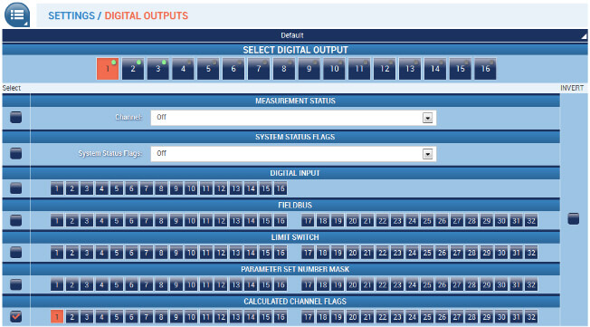
Output of Flags to the digital outputs 1 (Track 1, Flag 01) etc.

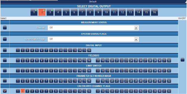
Output 2 = Flag 02, Track 2:

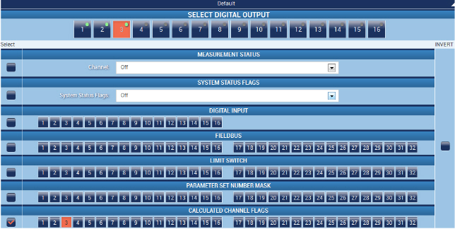
Output 3 = Flag 03, zero scale mark:

Tips

Properties of the PX878 outputs

It is essential to observe the electrical properties of the outputs. The frequency should not exceed 1 kHz. The output voltage of 10..30 V needs to be externally applied. High-side drivers are involved, if necessary, a pull-down resistor needs to be connected to GND, or differential outputs are set.

Differential outputs

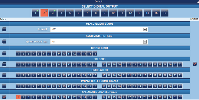
Should differential outputs be required, a Flag needs to be assigned in parallel to two digital outputs. The second output is inverted. This doubles the number of outputs. Here, Flag 01 was assigned to output 2, which is inverted:

Update rate of outputs

The digital outputs are updated with 2.4 kHz by default. Should the outputs' pulse widths vary too much (jitter), the rate should be increased.

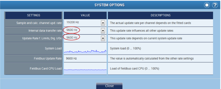
This is done via the Settings -System -Device -System Options menu. At first, the "Internal data transfer Rate" needs to be increased, then "Update Rate f. Limit, Dig. I/Os". The system load needs to be monitored.

Note:

Depending on the device specifications (e.g. with CODESYS), it may not be possible to increase the update rates.

Negative s values This example uses only positive s values. If the input signal also has negative values, a constant multiple of resolution could be added such that s is always positive, e.g.s = s_original + 1000.

The "Zero Value" in the amplifier settings is another option. This value enables the measured value to be turned into a positive value.

The shifting of the measured value does not impact on the periodic modulo functions, however, the switching thresholds of the zero scale mark need to be adapted, if necessary.

Legal notice

These examples are for illustrative purposes only. They cannot be used as the basis for any warranty or liability claims.