Glossario Forze Glossario Forze | HBM

Force Measurement Glossary: The Characteristics of Force Transducers

Look up the most important technical terms in the field of force measurement in this practical online force measurement glossary.

Standards, Guidelines, and General Information

DIN EN ISO 376 

DIN EN ISO 376 describes a calibration process for force transducers or measurement chains (generally referred to as force-proving instruments in the standard), which is employed for transducers that are to be used as reference force transducers or transfer standards, or is applied when there are stringent requirements for the determination of measurement uncertainty.  The procedure involves preloading with nominal (rated) force several times, step by step, loading over eight or ten load stages in three mounting positions each rotated by 120°, and a creep measurement.  

Next, each calibrated force transducer is provided with a calibration certificate, which states the transducer’s class and evaluates and documents the characteristic values. The calibration certificate also contains information on the standard test machine used, the signal conditioner employed, and the ambient conditions prevailing during calibration (temperature, air pressure, etc.) 

Tip: You can find an interactive calibration certificate here. The individual elements of calibration as per DIN EN ISO 376 are explained step by step. 
VDI/VDE 2638

VDI/VDE 2638 defines characteristic quantities for force transducers, with the aim of creating a uniform language and technical understanding. The standard was issued by the Association of German Engineers VDI.

Degree of protection as per EN 60529  

The degree of protection (also referred to as IP code or ingress protection code) indicates how well an item of equipment is protected against the ingress of foreign bodies and moisture. The rating consists of a two-digit number, for example, IP67. The first digit describes the level of protection against the ingress of solid objects, the second the level of protection against the ingress of moisture. 

Example: IP67 – Dust-tight, protection against temporary full immersion to a maximum depth of one meter for 30 minutes.  

Tip: You can find an article from HBK weighing technology containing further useful information about IP ratings here.  

Mechanical shock resistance as per IEC 60068-2-6

Mechanical shock resistance indicates the extent to which a transducer can be subjected to mechanical stress. 

Standard IEC 60068-2-6 describes a drop test used, for example, to determine the number of shocks and the acceleration. Details of characteristic quantities can be found in the data sheet specifications or in the operating manual of the transducer in question.

Vibrational stress as per IEC 60068-2-27

Standard IEC 60068-2-27 describes the procedure for determining the fatigue strength of equipment. For HBK force transducers, this means that they are exposed to a frequency that varies between 5 and 65 Hz. Further details of characteristic quantities (acceleration, number of repetitions) can be found in the data sheet or operating manual. 

Reference transducers/transfer standards

Transducers that satisfy the requirements of an ISO 376 accuracy class are referred to as reference force transducers or transfer standards. These transducers achieve defined accuracy classes in a given measurement range, for example, the C15 force transducer achieves accuracy class 00 as per DIN EN ISO 376 in a measurement range between 10% and 100% of the nominal (rated) force.

Back to top

Characteristic quantities as per DIN EN ISO 376

Accuracy class as per ISO 376 

Force transducers calibrated according to ISO 376 are assigned to accuracy classes. The highest accuracy class is 00, followed by 0.5, 1 and 2. 

For each of the features mentioned below, there is a limit value for each of the four accuracy classes. Therefore, if all features of a force transducer, with the exception of repeatability, can be assigned to the most accurate class (00), the transducer overall is allocated to the class that it achieves in terms of repeatability at this load stage.   

The following features are evaluated:  

Note: A lower accuracy class indicates a more accurate transducer  

Relative error of reproducibility/reproducibility (b); [%]

The error of reproducibility indicates the difference in the arithmetic mean of the load stage in question in a different mounting position. This procedure is set out in ISO 376. After installation, the force transducer is subjected to step by step loading in one mounting position, then removed, rotated 120° and re-installed. When the series of tests is completed in this new position with the same load stages as the first series of tests, the transducer is removed once more, rotated 120° in the calibration machine, and another measurement performed, also at the same load stages. The results of each load stage are then used to calculate the reproducibility. Therefore, the calibration certificate shows a reproducibility figure for every calibration stage. This figure is stated relative to the measuring force.

Relative error of repeatability/repeatability (b`); [%]

Repeatability signifies the deviations in the current load stage in an unchanged mounting position. Hence, the figure shows how well a transducer reproduces in its fixed mounting position. For this test, the transducer is exposed to the same load stages twice without any removal or re-installation. On the calibration certificate, this  error of repeatability is stated relative to the measuring force.

(Relative) error of interpolation (fc); [%]

With reference force transducers (U15, top class transducers, …), the interpolation error is shown relative to the measured value. As a rule, calibration as per ISO 376 does not produce a characteristic value as a measure of sensitivity, but a function. Accordingly, the interpolation error is the difference between the real characteristic curve of the transducer from the function that represents the calibration result.  

Important: This contribution to measurement uncertainty is not stated relative to the full-scale value, but relative to the measured force. At HBK, the relative error of interpolation is shown as a third-degree function on the calibration certificate. 

(Relative) zero error (f0); [%]

The relative zero error indicates the deviation of the zero point. To determine the zero error, the zero signal is plotted after a loading and unloading cycle and is a measure of the zero point return. 

Relative error of reversibility/hysteresis (v); [%] 

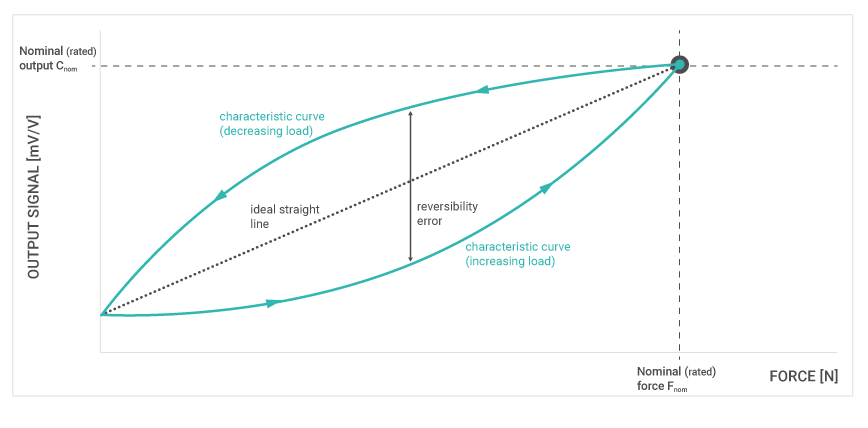
The relative error of reversibility (hysteresis) describes the difference in the characteristic curve as the load increases or decreases. At HBK, the maximum possible deviation of the curve is always stated on the data sheet. Therefore, the hysteresis of the individual transducer is likely to be (much) smaller than the values given on the data sheet. 

The indication of the reversibility error as per DIN EN ISO 376 is not ascertained at a fixed force (see relative reversibility error/hysteresis as per VDI/VDE 2638), but in a range (for example, 10% … 100% of Fnom). 

On the calibration certificate, you will see the hysteresis for each applied load stage.  

Creep (c); [%] 

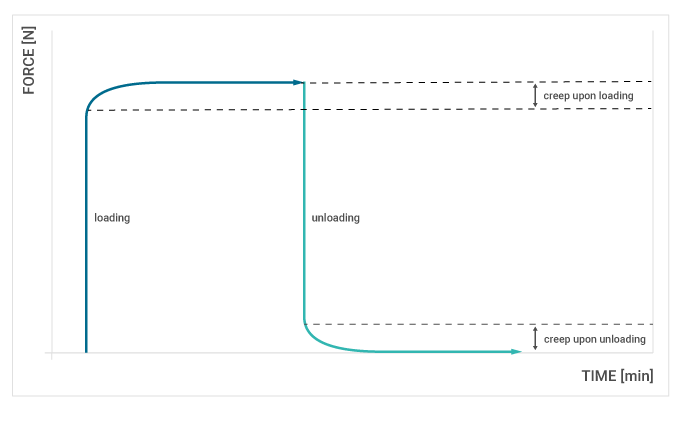
Under constant load, strain gauge-based transducers show a slight change in signal similar in form to an e-function. This process is known as creep after loading. If the force is removed, the signal changes in approximately the same way in the opposite direction. This is referred to as creep after unloading.  

The maximum signal variation is stated in percent relative to the applied force, not relative to the nominal force (Fnom). Similarly, the time stated is that at which the signal variation was determined – typically after 5 or 30 minutes. 

Since the profile takes the form of an e-function, it is a very good approximation to indicate the figure on the data sheet as a creep maximum. This figure cannot be extrapolated in a linear fashion; hence, creep does not double if the observation time is doubled.

Accuracy

HBM accuracy class

The accuracy classes of transducer manufacturers are not governed by any standards or standardization. At HBK, the HBM accuracy class is calculated from the largest individual characteristic. To do this, the following force transducer characteristic quantities are considered: 

The accuracy class can help to select the individual components of a measurement chain in such a way that they have roughly the same accuracy class. 

As accuracy classes are defined by the manufacturers themselves, it is not possible to compare the metrological components of different manufacturers based on accuracy class.  

Note: At HBK, a lower accuracy class indicates a more accurate transducer. 

Relative repeatability errors in an unchanged mounting position (brg); [%]

Relative repeatability errors indicate the difference in the arithmetic mean of the current load stage in an unchanged mounting position. This figure, therefore, shows how well a transducer reproduces in a given mounting position. For this test, the transducer is exposed to the same load stages twice without any removal or re-installation.

Relative reversibility error/hysteresis (v0.4; v0.5); [%]

The reversibility error (hysteresis) describes the difference in  transducer output readings as the load increases and decreases. On the data sheet of the force transducer in question, you will see the force (for example, 0.4 * Fnom = at 40% of the nominal force) at which the figure was achieved. At HBK, the maximum deviation of the curves is always stated. Therefore, the hysteresis of the individual transducer is usually smaller than the value given on the data sheet. 

(Relative) linearity error (dlin); [%]

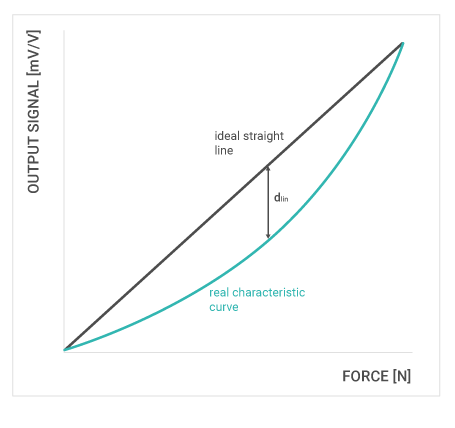
The linearity error describes the deviation of the real characteristic curve from an ideal straight line.  

Non-linearity is indicated relative to the nominal (rated) force (in other words, the full-scale value). Calibration helps to minimize measurement uncertainty caused by non-linearity. Therefore, we recommend performing calibration in the force range in which the transducer will subsequently be used (sub-range calibration). 

At HBK, the maximum possible non-linearity is always stated on the data sheet, that is, no transducer has greater non-linearity than that indicated on the data sheet.  

Relative zero (point) return [%]

Relative zero-point return describes the zero signal after the force transducer has been loaded with its nominal force. 

Relative creep (dcr, F; dcr, E); [%]

Under constant load, strain gauge-based transducers show a slight change in signal that resembles the form of an e-function. This process is known as creep after loading. If the force is removed, the signal changes in approximately the same way in the opposite direction and is referred to as creep after unloading.  

The maximum signal variation is stated in % relative to the applied force, not relative to the nominal force (Fnom). Similarly, the time stated is that at which the signal variation was determined – typically after 30 minutes. 

Since the profile takes the form of an e-function, it is a very good approximation to indicate this figure on the data sheet as a creep maximum. This figure cannot be extrapolated in a linear fashion, so creep does not double if the observation time is doubled.  

Effect of the bending moment [bending moment effect] (dMB); [%]

The  bending moment effect indicates the influence of a bending moment on the output signal of a force transducer and can therefore be used to determine measurement uncertainty. 

The figure in the force transducer specifications describes the deviation in percent at a fictitious bending moment, which can be calculated as follows: 

Mb fiktiv= 10% of Fnom* 10 mm.  

Example: Let us assume the force transducer has a nominal force of 250 kN. The effect of the bending moment mentioned in the specifications is 0.01%. Thus, the bending moment that causes this effect is: 

10% of Fnom * 10 mm à 25,000 N * 0.01 m = 250 Nm 

With an acting bending moment as above, the maximum effect is 0.01% of the full-scale value (250 kN in our example), in other words: 

This contribution to measurement uncertainty grows in linear fashion as the acting bending moment increases, that is, an acting moment of 500 Nm results in 50 N, and at a bending moment of 125 Nm, the maximum effect is 12.5 N. 

Also pay attention to the bending moment limit (dMB) stated in the specifications. 

Effect of lateral forces [lateral force effect] (dQ); [%]

The effect of lateral forces describes the influence of a lateral force on the output signal. This figure is established at a lateral force of 10% of the nominal force (Fnom). This contribution to measurement uncertainty is calculated relative to the full-scale value (nominal force).  

Effect of eccentricity [eccentricity effect] (dE); 

The effect of eccentricity describes the effect of eccentric force application. The effect is calculated by multiplying the eccentricity used in the field by the figure on the data sheet and the applied force. 

Example: A force transducer is subjected to a load of 200 kN and an eccentricity of 10 mm. In the specifications, the effect of eccentricity is stated as 0.04%/mm. 

The effect of eccentricity is therefore 


Temperature coefficient of zero signal (TK0; TC0); [%/10 K]

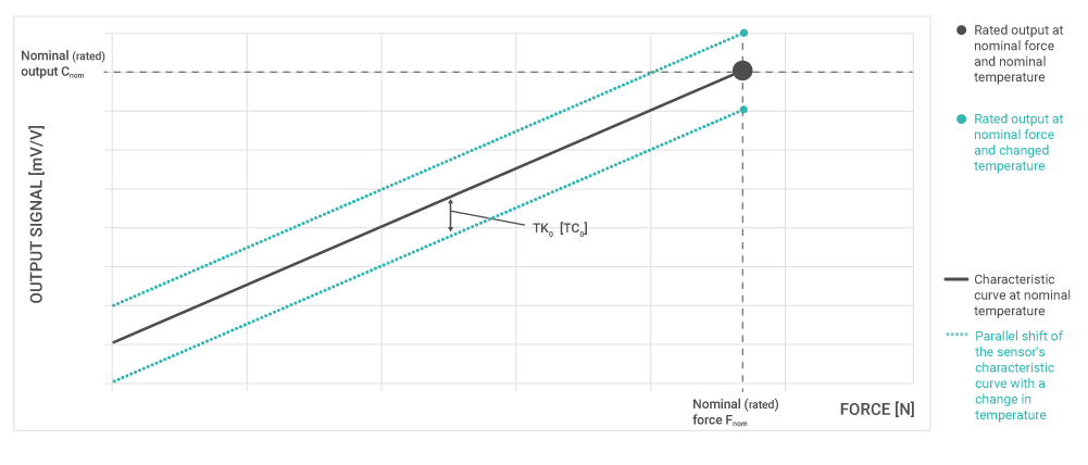
The zero signal of a force transducer changes slightly with the temperature. This effect is largely compensated by the Wheatstone bridge circuit and other measures, so that modern force transducers have a residual error of less than 0.015% per 10 K.  

The temperature effect (TC) of the zero signal must always be calculated relative to the nominal force (Fnom), irrespective of what force is measured. For this reason, for work with larger temperature variations and/or in partial load, we recommend using a force transducer that has an especially low TC0.

HBK specifies the TC0 of force transducers in such a way that all specimens are within the limits defined on the data sheet. Consequently, no specimens are delivered that do not comply with the data sheet figures.

Temperature coefficient of sensitivity (TKC; TCS) [ %/10 K] 

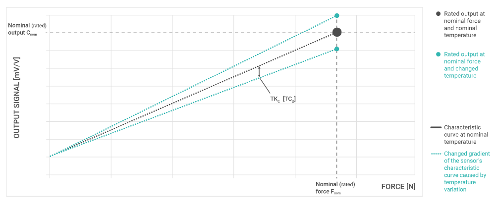
Strain gauge-based force transducers change their sensitivity slightly when the temperature changes.This happens because the modulus of elasticity of the material gets lower as the temperature rises. Therefore, the same force results in greater strain and, therefore, a higher output signal. The gauge factor (proportionality factor between change in resistance and strain; the sensitivity of a strain gauge) of strain gauges is temperature dependent. 

At HBK, the resulting temperature effect of sensitivity is compensated during transducer production and is, therefore, very low. 

No specimen delivered by HBK has a higher TCS than that stated on the data sheet.  

Electrical characteristics

Zero signal

The zero signal is the output signal of the force transducer when upright and not installed. It can change due to the mounting of attachments and transducer pre-stressing. 

Like the relative zero signal error, the zero signal is not a measurement error and can be eliminated by taring or setting to zero. 

 Relative deviation of the zero signal  (ds,0); [%]

The relative zero signal error indicates the maximum deviation of the zero signal at reference temperature without attachments or load, in an upright position. The stated zero error is not a measurement error and is important for selecting a suitable signal conditioner, because a zero error influences the maximum output signal. It is therefore possible for the output signal of the force transducer to lie outside the input range of the signal conditioner.

Rated output [Characteristic value](C)

The rated output denotes the output signal that is produced when the force transducer is subjected to its nominal  force (Fnom). Any potential zero signal is deducted. The figure is stated in mV/V. 

Example: A transducer has a zero signal of  –0.1 mV/V. At a rated output of 2 mV/V, there is an output signal of 1.9 mV/V at nominal force if it was not previously set to zero.  

A rated output of 2 mV/V signifies that a force transducer produces an output signal of 2 mV if it is supplied with one volt. Consequently, the output voltage is 10 mV at a transducer supply of 5 V. The applied output voltage is calculated as follows: 

  • U Output voltage 
  • U0  Transducer supply 
  • C Rated output 
  • F Acting force 
  • Fnom Nominal force 

Please note that in this formula, the zero signal is assumed to be an ideal zero or is based on a measurement where zero was previously set.

Rated output range (C); [mV/V]

Some force transducers can be purchased without a calibrated rated output. For these transducers, the rated output is stated in a range referred to as the rated output range (C) in the transducer specifications. Typical rated output ranges are  2 mV/V … 3 mV/V or 4 mV/V … 4.8 mV/V.  

The individual rated output of a transducer can be found in the enclosed test report or stored in a TEDS (Transducer Electronic Data Sheet) chip, if present. 

Nominal rated output (Cnom); [mV/V]

The nominal rated output is the rated output for which a force transducer has been designed. During the production of force transducers, manufacturing tolerances give rise to scatter, so that the rated output of an individual transducer may differ from the nominal figure. This is indicated by the rated output tolerance (dc).  

A test report is enclosed with every HBK transducer, showing the precise rated output for the individual transducer. An exception applies to transducers that are only calibrated following installation, for example, force washers of the KMR+ or CFW series.  

Frequently, the rated output of a force transducer is already calibrated during production, so that all transducers of the same type receive one rated output with extremely narrow tolerances. Alternatively, rated output calibration can be selected as an option. Typical rated outputs are 2 mV/V or 3 mV/V. 

Tip: To ensure optimum measurement accuracy, always adjust the signal conditioner in line with the data in the test report or an existing calibration. In this case, the rated output tolerance has no influence on the accuracy of your measurement. 

Transducers can also be ordered with a TEDS. In this case, a chip containing the precise data from the test report or calibration is installed in the transducer or cable. Suitable signal conditioners can read this data and automatically adjust themselves accordingly. 

Relative rated output tolerance (dC); [%]

This indicates the permissible deviation in percent of the individual rated output of a force transducer from the nominal rated output. If the test report (provided with every transducer) or a calibration certificate is used to adjust the signal conditioner, this is neither a measurement error nor a limitation on accuracy.

Relative rated output variation (tension/compression) (dZD); [%] 

Force transducers that can be used for tensile or compressive loading, for example, transducers from the U3, U9C or U15 series, frequently have a minor difference in their characteristic curve, depending on whether they are used for measuring tensile or compressive forces. 

The maximum difference between the curves is described by the characteristic of relative rated output variation (tension/compression). 

Input resistance (Re); [Ω]

The input resistance is the resistance measured between the input voltage connections. As the Wheatstone bridge circuit is provided with several resistors that help to balance the force transducer, the values for the input and output resistance may differ.

Please note that the overall resistance of the circuit falls when force transducers are connected in parallel. This figure must not fall below the overall resistance limit stated in the operating manual of the signal conditioner. 

Output resistance (Ra); [Ω]

The output resistance is the resistance measured between the output voltage connections. When force transducers are connected in parallel, the output resistance tolerance must be very small, as otherwise cross currents can influence the measurement result.  

HBK has force transducers that are suitable for connection in parallel.   

Insulation resistance (Ris); [Ω] 

The insulation resistance is the resistance between any connecting cable and the measuring body. It is measured at room temperature by applying a test voltage to the transducer’s internal wiring via a connecting cable and measuring the resistance to the measuring body. If the measured value does not match the figure on the data sheet, the transducer must be replaced as the characteristics can no longer be adhered to.

Operating range of the excitation voltage (BU,G); [V] 

The excitation voltage is the force transducer supply voltage and is stated in range, for example, 0.5 V to 12 V.  

If the maximum excitation voltage is exceeded, this may cause the strain gauge to become too hot, resulting in a change in the zero point (see TK0/TC0) and a change in sensitivity, and therefore in the rated output (see TKS/TCS).

Reference excitation voltage (Uref); [V] 

The reference excitation voltage, which is generally 5 V, is used to determine all the force transducer characteristics. For high-precision measurements, we recommend using this excitation voltage or, alternatively, ordering a measurement chain calibration.

6/4-wire circuit 

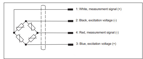
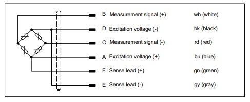
HBK force transducers are designed with a 4 or 6-wire circuit as standard. The load cell itself and the connecting cable form a voltage divider, that is, the higher the cable resistance, the lower the voltage to the strain gauge of the force transducer. A lower voltage to the Wheatstone bridge now results in a lower output signal: the rated output of the force transducer changes with the resistance of the mains cable.  

In a 6-wire circuit, the voltage is measured directly at the strain gauge bridge by means of two additional cables and corrected if necessary. Therefore, the sensitivity (rated output) is independent of the cable length or temperature. It is a particular advantage that the effect of the cable resistance is continuously adjusted, that is, even if the mains cable resistance changes due to temperature or a change in cable length, this has no influence on transducer sensitivity. The 6-wire configuration is primarily used for high-precision transducers. 

If a force transducer with 6-wire configuration is to be connected to a signal conditioner with 4-wire configuration, we recommend short-circuiting the sense leads with the corresponding excitation voltage leads. The ohmic resistors of the supply cable will then be lower, reducing the voltage drop at the mains cable and, therefore, the effect of the cable length and potential temperature influences. If you need to take very precise measurements using a signal conditioner with 4-wire configuration, we recommend measurement chain calibration to eliminate cable influences. 

For force transducers with 4-wire configuration, the connecting cable belongs to the calibration network – do not shorten cables; extend them to a 6-wire configuration if possible, to prevent a worsening of sensitivity and the effect of temperature on the rated output.  

Important temperature data

Reference temperature (Tref); [°C, °F] 

The reference temperature indicates the temperature at which all non-temperature-dependent measured values are determined. 

The reference temperature is identical for transducers with and without integrated amplifiers. The reference temperature for HBK force transducers is 23 °C.

Nominal temperature range (BT, nom); [°C, °F] 

The nominal temperature range denotes the range in which the force transducer complies with the specifications. 

Note: Please note that the nominal temperature range of a force transducer with integrated amplifier will differ from that in versions without an amplifier module. 

Operating temperature range (BT, G); [°C, °F] 

The operating temperature range signifies the temperature range in which measurements are possible with the force transducer, but limited accuracy must be expected. 

Note: Please note that the operating temperature range of a force transducer with integrated amplifier will differ from that in versions without an amplifier module. 

Storage temperature range (BT, S); [°C, °F] 

The storage temperature range indicates the range in which the force transducer can be stored without suffering damage. However, the transducer must not be used for measurements. 

Note: Please note that the storage temperature range of a force transducer with integrated amplifier will differ from that in versions without an amplifier module.

Back to top

Mechanical characteristics

Nominal (rated) force (Fnom); [N] 

The nominal force defines the force at which the force transducer reaches its nominal output, indicating that it is at 100% load. Within this force range, all the specifications on the data sheet are adhered to.  

When designing your test setup, please bear in mind that tare loads, for example, due to the intrinsic weight of fitted attachments, need to be included in calculation and take up some of the nominal force. 

In the case of dynamic load, pay attention to the relative permissible oscillation stress (frb). 

(Relative) maximum operating force (FG); [%] [N] 

The maximum operating force defines the force up to which the force transducer can be used a few times without suffering any damage. The maximum operating force is stated as an absolute figure (in newtons) or relative to the nominal force (Fnom) in %. The operating force range is used, for example, for pre-stressing threads during installation.  

We recommend selecting a force transducer in such a way as to ensure that there is no need to use the maximum operating force.  

(Relative) force limit (FL); [%] [N]

The force limit is stated as an absolute figure in newtons or relative to the nominal force (Fnom) in %. If the force transducer is loaded above its force limit, the transducer may be damaged and may no longer be suitable for use.  

The force transducer frequently undergoes plastic deformation following load above the force limit, which is evident from a marked change in the zero point. If this occurs, the transducer must no longer be used, and should be replaced or checked by HBK.  

(Relative) breaking force (FB); [%] [N]

The breaking force is also stated as an absolute figure in newtons or relative to the nominal (rated) force (Fnom). If this force is reached, the force transducer may break.

Please follow the safety instructions in the force transducer operating manual. 

Torque limit (MG); [N∙m] 

The torque limit signifies the permissible torque acting around the measuring axis of the force transducer which, under simultaneous load with nominal force (Fnom), does not result in lasting damage to the transducer or an associated change in the transducer characteristics.  

Bending moment limit (Mb zul); [N∙m] 

The bending moment limit signifies the permissible bending moment acting around the measuring axis of the force transducer, which does not result in lasting damage to the transducer or an associated change in the transducer characteristics.

A bending moment can be produced by the introduction of an eccentric force or a lateral force. 

Maximum eccentricity (eG); [mm] 

Maximum eccentricity is the maximum permissible distance between the acting force vector and the centre of the force transducer.  

Note: Eccentricity always produces a bending moment as well. The general rule is: bending moment = acting force * eccentricity. Please read the section on the bending moment limit.  

(Maximum) static lateral force limit (FQ); [%] 

This indicates the permissible (maximum) static lateral force limit which, under simultaneous load with nominal force (Fnom), does not result in a permanent change to the transducer characteristics. It is stated in % relative to the nominal force.

Nominal (rated) displacement (snom); [mm]

The nominal (rated) displacement indicates the extent of deformation of a force transducer in the measuring grid direction when it is subjected to nominal force (Fnom).  

Resonance frequency (natural frequency)(fG); [kHz] 

Like every mass spring system, force transducers also have a natural frequency, which can be calculated using the following formula: 

  • Cax Stiffness 
  • m Oscillating mass 
  • fG Natural frequency 

The natural frequency in the specifications only takes the oscillating mass of the force transducer into consideration, and not that of the required attachments. The natural frequency of the system changes when additional masses are mounted on the transducer.  

If a force transducer is intended for dynamic use, the installation situation, including the overall stiffness of the system and the sum of oscillating masses, must always be taken into consideration. 

Tip: As a rule of thumb, the static calibration of a force transducer can be used up to 20% of the natural frequency of the overall system. 

Relative permissible oscillation stress (Frb); [%] 

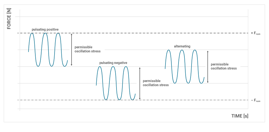
The relative permissible oscillation stress is stated as a quantity in % relative to the nominal force (Fnom). The permissible oscillation stress describes an oscillation width (peak-to-peak), that is, the difference between the highest and the lowest force, whether pulsating or alternating, to which the force transducer may be subjected.  

Example: A force transducer for tensile and compressive loading has a nominal force (Fnom) of 200 kN, and the relative permissible oscillation stress is 100%. Therefore, the force transducer may be subjected to a force between 0 and 200 kN, but also  –100 kN and 100 kN.  

Please follow the safety instructions in the force transducer operating manual. 

Tip: Transducers with an oscillation width of 200% can be permanently used within their full tensile and compressive force measuring range. 

Stiffness/rigidity (cax); [105N/mm]

The stiffness of a force transducer is the relationship between nominal force (Fnom) and nominal displacement (Snom). It is influenced to a large extent by the transducer’s basic design and its nominal force, and is calculated as follows: 

  • Cax Stiffness 
  • Fnom Nominal force 
  • Snom Nominal displacement 

Stiffness is needed to calculate the natural frequency of a force transducer. 

Back to top

Additional information for force transducers with integrated amplifiers

VA1/VA2

Some force transducers can be purchased with an integrated amplifier (for example, U2B, C2, C6B), or an inline (cable-integrated) amplifier is available. These force transducers transmit an output signal in volts (VA1) or milliamperes (VA2). 

Output signal  

The output signal of a force transducer with permanently connected amplifier is stated in a given range. This is 0 V – 10 V for a transducer with voltage output (VA1) and 4 mA – 20 mA for a transducer with current output (VA2).

Nominal (rated) output

The nominal rated output is the signal that a force transducer delivers when subjected to nominal  force (Fnom). This may be 10 V or 20 mA, for example.  

Rated output tolerance

The rated output tolerance indicates the permissible deviation of the rated output from the nominal output.

Zero signal (with integrated or cable-integrated amplifier) 

The zero signal is the signal delivered by the force transducer when it is not under load. The zero signal differs in transducers for tensile and compressive forces (for example, U2B) and simple compressive force transducers (for example, C2). If the transducer has a current output, the zero value for transducers that can only be used for compressive forces is 4 mA, and if it has a voltage output, the zero value is 0 V. For force transducers designed for both tensile and compressive forces, the zero point is 12 mA or 5 V. 

Output signal range

This indicates the range within which the amplifier module supplies an output signal (for example, 0.3 V – 11 V). 

Please note that a higher load does not result in a higher output signal if the full-scale value is reached. This can mean that transducer overload is not recognized, and the transducer suffers lasting damage.

Cut off frequency [kHz]

The cut off frequency is the maximum frequency that the amplifier module can amplify. This value is usually stated with an attenuation of 3 dB. 

Supply voltage range [V] 

The supply voltage is that required by a force transducer with integrated amplifier and is stated as a range (for example, 19 V – 30 V). If the voltage is above or below this range, this can lead to incorrect measurements and, in extreme cases, cause irreparable damage to the transducer. 

Nominal supply voltage [V]  

The nominal supply voltage must be identical to the nominal output voltage of the power supply.  

Maximum power consumption [mA]

This indicates the maximum power consumed during operation by a force transducer with integrated amplifier. It differs in transducers with a voltage output (VA1) and those with current output (VA2). 

Find out more about amplified load cells (N) and force sensors

Part of the HBK force measurement portfolio is optionally available with an integrated amplifier and a voltage or current output. Find out more about the benefits of force sensors with 0… 10 V or 4…. 20 mA output signals.

View force sensors with integrated amplifiers               Sign up for a free webinar: The Pros and Cons of Amplified Force Sensors

Additional information for piezoelectric transducers

Sensitivity (S); [pC/N]

The sensitivity of a piezoelectric force transducer describes the change in charge in picocoulombs per newton of acting force. Sensitivity is the slope of the transducer characteristic curve. 

Example: A piezoelectric force transducer with a sensitivity of 4 pC/N undergoes a change in force of 100 N, and so its charge changes by 400 pC.

Crosstalk [N/N][N/Nm]

Crosstalk is a physical phenomenon in piezoelectric transducers. When a force is applied in a direction other than the measuring grid direction (lateral force), there is a minimal change in the output signal, which is added onto the actual measurement signal. The extent of this change is defined as crosstalk in the specifications. Please note that Fz is the measuring axis.

Maximum bending moment (Mb, zul); [Nm] 

The design of piezoelectric force transducers is such that they may only experience a bending moment that is maximum 50% of the nominal force when they are under load. Due to this design principle, when no force or maximum force is applied, the maximum bending moment is zero.  

Note: Please note that the maximum bending moment of piezoelectric force transducers is an independent characteristic from the bending moment limit. 

Drift

Piezoelectric force transducers undergo very slight losses of charge inside the measurement electronics over time. This is due to imperfect insulation resistors, charge amplifier components and cables. The electronics are unable to distinguish between a change in charge due to charge losses and a change in charge due to a variation in the acting force. This drift is added to the actual measurement signal. 

This is a very minor effect, but nevertheless is particularly relevant if small forces are to be measured over a long period. The influence of drift can be eliminated by regular setting to zero or the use of high-pass filters.

Find out more about piezoelectric force sensors

The force measurement tips and tricks have an entire section dedicated to piezoelectric force transducers and the question when the technology is preferable towards strain gauge-based sensors, and when it isn’t.

Go to the force measurement knowledge base                                View the piezoelectric portfolio

Additional information for strain transducers

Nominal strain (ɛn); [μm/m]

Nominal strain is the strain when the transducer is at 100% load.

Maximum operating strain (ɛG); [%]  

The maximum operating strain indicates the strain up to which the transducer does not suffer any damage, if it is not used several times in this range. The maximum operating strain is stated in % relative to the nominal strain (ɛn).  

The dimensions of the transducer must be such that the maximum operating strain does not need to be used. 

Breaking strain (ɛb); [%]  

The breaking strain is also stated relative to the nominal strain (ɛn) . If this force is reached, the strain transducer may break.  

Please follow the safety instructions in the transducer operating manual. 

Restoring force (Fd); [N/µm]

The restoring force is the force in newtons that is required to bring the strain transducer to nominal strain. 

Relative permissible oscillation stress (peak-to-peak) (ɛrb); [%] 

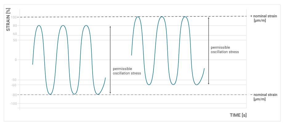
The oscillation width is a peak-to-peak value, that is, the difference between the highest and lowest strain and is stated in % relative to the nominal strain (ɛn). It is important to note that negative strains are also permitted. In this range, the strain transducer may be subjected to permanently alternating strain. 

Example: Accordingly, a strain transducer with a permissible oscillation width (peak-to-peak) of 160% may be subjected to alternating load between a negative strain of 60% and a positive strain of 100%, but also between a negative and positive strain of 80% of the nominal strain (ɛn). 

Acceleration sensitivity in the measuring direction (da, s; da, q)

Acceleration sensitivity in the measuring grid direction indicates the transducer error when it is exposed to acceleration. 

Still want to know more?

Register for our newsletters or enhance your force measurement know-how with our knowledge base: