力測定用電子機器の調整 力測定用電子機器の調整 | HBM

How Do I Correctly Adjust My Electronics to Match My Force Sensor?

Force transducers, or force sensors, differ from load cells in one important aspect: While load cells are installed in the weighing scale before the scale’s calibration, a force sensor is calibrated immediately after production and the result is recorded in the accompanying documents.

The requirement for the force transducer is, therefore, to reliably maintain the sensitivity that is determined during its calibration in the factory when used. To achieve this, the sensor must be mounted correctly. Correctly adjusting the measuring amplifier is also a very important step in the commissioning of each force sensor. This step, the so-called adjustment, ensures that the output signal of the force sensor can be interpreted correctly by your measuring amplifier system or software so that you obtain correctly measured values at the end of the day.
 

The Characteristic Curve of a Force Transducer

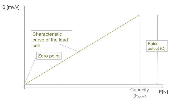
The result of the calibration measurement during production is documented and provided along with the force transducer; at HBM, this document is referred to as the "test record". The test record specifies the so-called rated output (symbol C) and has the unit mV/V.
What is the rated output (C)?

Strain gauge-based force transducers are passive sensors that are supplied with a voltage by a matching measuring amplifier. The rated output specifies the magnitude of the change in the output signal in the unit mV when the amplifier's transducer supply voltage is exactly 1 V and the applied force changes from zero to the sensor's capacity.

Measuring amplifiers do not always supply the force transducers precisely with 1 V; other excitation voltages, for instance, 2.5 V or 5 V, are frequently used in practice. In these cases, the output signal increases accordingly. A load cell with a rated output of 2 mV/V outputs a usable output voltage of 10 mV when operated at 5 V and 5 mV when supplied with 2.5 V.

To ensure that the specified rated output is independent of the excitation voltage and that the specified sensitivity is the same for all excitation voltages, the signal is standardized to 1 V—hence the unit mV/V. When configuring your HBK measuring amplifier, it does not matter which excitation voltage is used, the rated output is always the same.

In practice, a zero balance is performed before the calibration measurement begins, so that the measuring amplifier first displays 0 mV/V before a load is applied to the force transducer. For this reason, calibration certificates and test records always show 0 mV/V at force zero. Then, force is applied in steps up to the nominal (rated) force and the output signal is measured. The rated output is the difference between the output signal when no force is applied and the output signal when the nominal (rated) force is applied.

Example

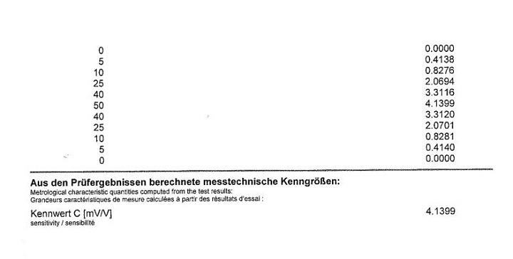
Figure 2 shows a test report of a C15/50kN. The nominal (rated) force of this force transducer is 50 kN. The measuring chain was zero-balanced before the measurement of the rated output; therefore, the output signal is 0 mV/V if no force is applied.

At the nominal (rated) force, i.e., 50 kN, the sensor outputs 4.1399 mV/V to the measuring amplifier.

As described above, the supply voltage is normally greater than 1 V—usually 2.5 V, 5 V, or 10 V. The force transducer's output voltage increases accordingly. The C15 in our example would provide an output voltage of 20.6695 mV when the rated force (50 kN) is applied and at an excitation voltage of 5 V.

The characteristic curve of a force sensor is not a perfectly straight line. Rather, there is a small deviation from the ideal straight line. Various amplifier and software solutions (such as HBK’s QuantumX or PMX systems for use in production processes) allow for the correction of this linearity error.

Adjusting the Measuring Amplifier

Adjusting measuring amplifiers during tests or in production environments using two-point scaling has become a well-established practice. The input differs from device to device; however, the following information is always entered:

0 N  corresponds tozero value mV/V
Rated force  corresponds torated output C in mV/V


In our above example, the following values can be found in the test record:

0 N  corresponds to0 mV/V
50 kN  corresponds to4.1399 mV/V


The voltage ratio, i.e., the normalization to 1 V in test records or calibration certificates, considerably facilitates the adjustment.

Characteristic Curve Setting for Active Force Sensors.

Force transducers that are permanently equipped with an amplifier module are also calibrated at the end of the production process. As with the passive sensors, the characteristic curve is determined and recorded in the accompanying documents.

At HBK, such measuring chains are calibrated as a whole, i.e. the relationship between the applied force and the voltage or current output signal is documented. This method has the advantage of the measuring amplifier already being adjusted. Setup is facilitated and accuracy is improved by performing a calibration of the complete measurement chain instead of calibrating the individual components.

As described above, two-point scaling has become established in the world of strain gauge-based sensors. However, force transducers with permanently connected amplifiers are connected to downstream data acquisition systems and PLCs of various kinds. Two-point scaling cannot always be used for parameterizing downstream electronics.

For this reason, HBK provides several types of rated output values for adjusting downstream electronics:

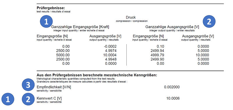
1. Two-point scaling, integer values for the force

This table shows the results of the production calibration, using integer force values. This specification corresponds to the specification that is also used for purely passive force transducers.

2.  Two-point scaling, integer values for the output signal (current or voltage)

This table describes the same characteristic as Table 1; however, integer values are given for the output signal; accordingly, the force values are no longer integers.

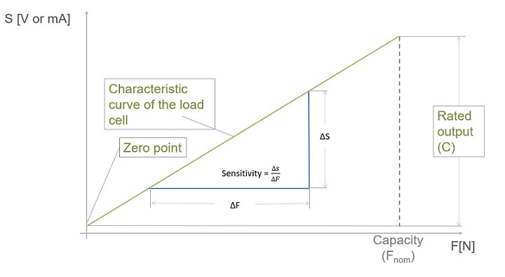
3. The sensitivity is given as a gradient (as is usual in piezo technology)

For example this value shows the change in output signal in volts (or mA) when the force changes by + 1 N. This information is particularly useful when switching from piezoelectric measuring systems to strain gauges or when the downstream electronics do not allow working with two-point scaling.

Of course, you will also find the rated output, i.e. the difference between the output signal at force zero and the nominal (rated) force. It is independent of whether Table 1 or 2 is used to calculate it. Both tables describe the same characteristic curve.