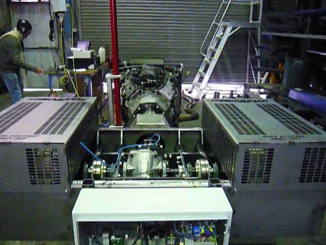
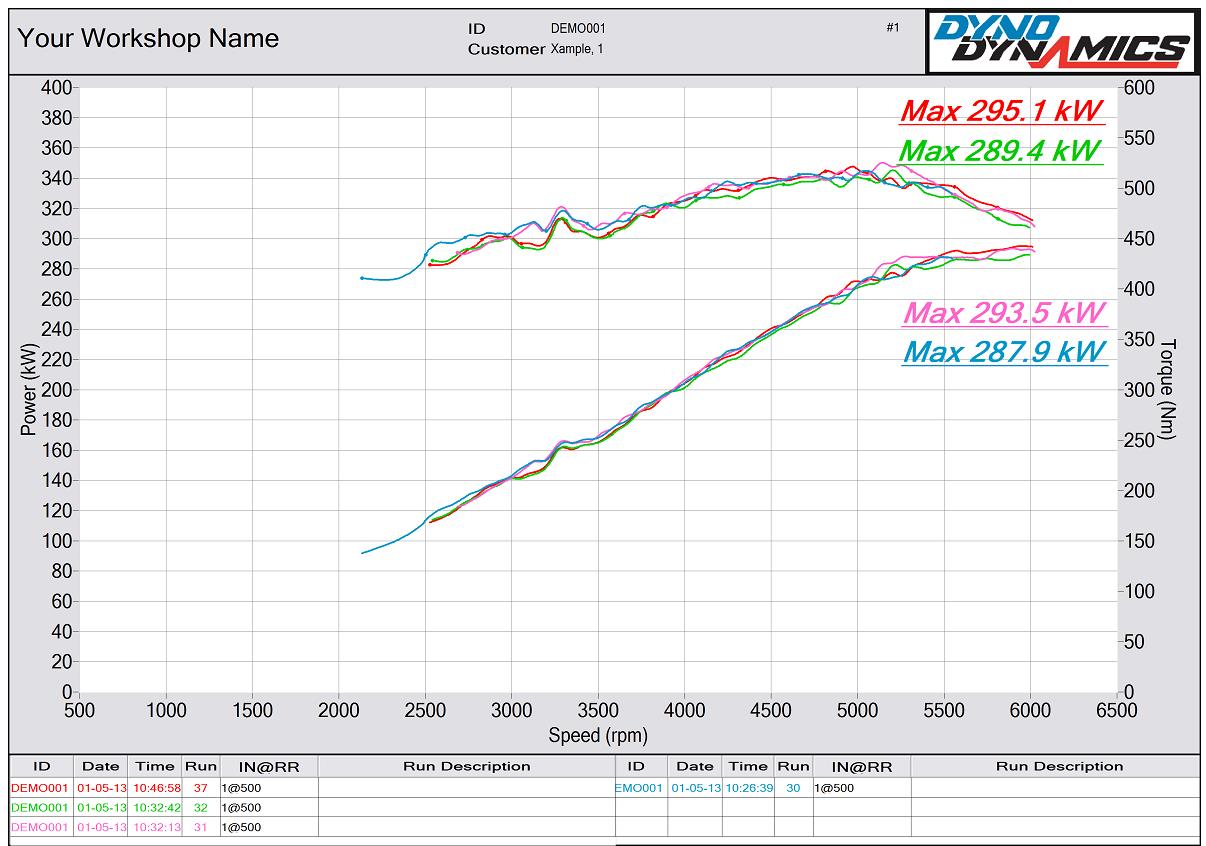
The Solution: A Torque-Damping Coupling
The rotational speed of an internal combustion engine is never constant. The crank is slowed down by each compression stroke, and accelerated by the power stroke. Although the engine’s flywheel averages out the rotation to some extent, there is still a pronounced speed (and torque) oscillation, especially at low revs.
This oscillation can cause severe stress on driveline components, and this is especially true with engine dynamometers/motors, where there is little “give” in the driveline; no tires or suspension to allow a little flex.
The solution is a torque-damping coupling. This is engineered to a precise torsional stiffness. Peak torques and rotational vibrations of the motor are largely neutralized through the use of the rotational vibration damper, thereby protecting the transmission from excessive wear.
The coupling Dyno Dynamics chose was a TECTOS t600, which is produced specifically for the engine test industry.
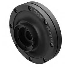
TECTOS t600
With the basic mechanical layout resolved, they focused on instrumentation.
At the heart of a successful dynamometer is accurate measurement of torque and speed. Additional data acquisition is usually required, but torque and speed are critical.
For speed measurement, they used their tried and tested toothed wheel / inductive pickup. These have proven reliable over many years.
Torque measurement was a different challenge. Accurate results require measuring the input torque to the gearbox, so as to include gearbox drag. This meant that Dyno Dynamics could not use the standard torque-reaction arm and load cell. A shaft torque transducer was required.
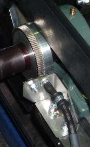
After extensive research, Dyno Dynamics decided on the HBM T40B. With a rating of 15,000 RPM /2,000 Nm, it matched the dynamometer design specs, and its compact profile allowed for a simple mounting layout.
The T40B is a flange-type sensor, with contactless signal transmission. This allows a very compact mounting profile, as the sensor is only 59 mm deep .
The HBM torque transducer was too responsive and required additional software filtering to smooth out individual cylinder pulses.
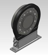
T40B
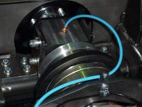
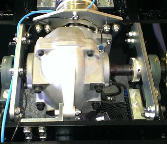
This photograph shows the sensor in-situ: black antenna ring mid-picture
