Experimental residual stress analysis using the hole-dril Experimental residual stress analysis using the hole-dril | HBM

Experimental residual stress analysis using the hole-drilling method on plastic materials

This article describes application of an automatic hole-drilling residual stress measurement system to polymeric moldings. An accessory has been developed for the Restan MTS3000, an automatic measurement system, essentially consisting of a very low-speed electric motor and an electronic control system.

1. Introduction

Over the last fifty years, the plastics industry has developed greatly, outstripping the steel industry also in technical applications. This has led to new synthetic substances progressively replacing traditional materials and to a formal rethinking of structures, ergonomic shapes and production processes.

What has made use of these materials become so widespread is essentially the fact that they are cheap, light, easy to work and it is possible to design the desired mechanical properties. Increasingly accurate and in-depth mechanical characterization is therefore necessary and it is in this context that the need arises to know and study thevalue of residual stresses induced by machining processes in these materials.

Also polymer melt flow, pressure distribution, non-uniform temperature field, and density distribution all cause residual stresses in polymer injection moldings and these stresses affect the mechanical properties of plastic parts, can alter the final shape and significantly reduce the life expectancy of the product, in addition to increasing the likelihood of dimensional instability and environment stress cracking. Although residual stresses are commonly found in plastics their magnitude can be difficult to predict, as it depends upon a wide range of variables including the mold design, material and processing parameters. Consequently, it is important to have a reliable technique to evaluate the stresses existing in plastic components.

The hole-drilling strain gauge method allows residual stress to be measured in a wide range of plastic moldings. It has the advantage that the measurements can be made over a smaller area. A special strain gauge rosette is bonded to the surface of the specimen and a hole is drilled precisely through the center of the rosette. The strains measured at the surface correspond to the stresses relaxed during the drilling process. Using the measured strains and appropriate models (i.e. ASTM E837) it is possible to calculate the stresses along the two principal axes and their direction.

2. Measurement system

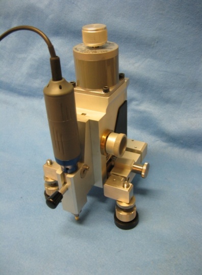
The mechanical setup of the drilling system is shown in figure 1a. It is based on the consolidated Restan - MTS 3000 system developed by SINT Technology and marketed in collaboration with HBM.

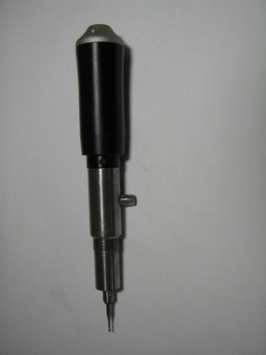
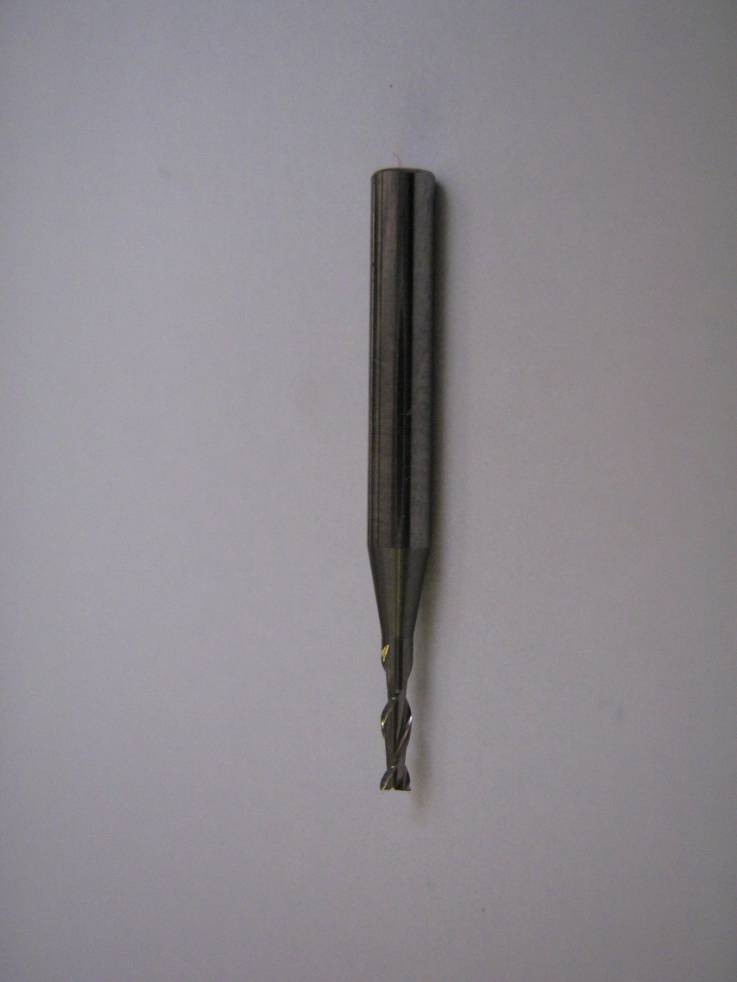
Figure 1b shows the specially designed drilling tool that allows holes to be drilled at under 200 RPM. This speed minimizes local heating and residual stresses induced in the material to be analyzed. The cutting tool is shown in figure 1c. It is a twist drill with two cutting edges perpendicular to the direction of advancement, 1.6 mm in diameter, which produces flat-bottom holes at modest feed rates.

The drilling system is powered and automatically controlled by the electronic control system and drilling control software, thus making the drilling process fully automated. The whole measurement apparatus may be remotely operated: this option is advisable as it allows the external influences of the operator to be minimized during the measurement process.

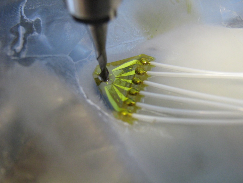
Figure 2 shows a three-element strain gauge rosette of the prewired type, which is preferable for the tests as it not only makes it faster to install but also means no heat is generated by welding wires.The residual stresses existing in the test component are determined starting with the strain values measured by the grids of the strain gauge bonded on the surface of the component.

The acquired data was processed using a special version of the EVAL software, produced by SINT Technology srl, specifically for processing the strains in plastic materials. This version applies an initial optimized polynomial interpolation of measured strains. The strain measurements are processed in conformity with the provisions of standard ASTM E837.
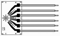
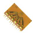
Figure 2 - Rosette: HBM K-RY61-1.5/120R-3 prewired
3. Test procedure

The main operations to be carried out when applying the hole-drilling strain gauge method to plastic materials are described below.

  • Clean the surface with a suitable cleaning agent for removing any dirt that can prevent the strain gauges from bonding to the surface of the polymer.
  • Attach the strain gauges to the surface of the polymer using an adhesive that has no afeect on the properties of the polymer. A cyanoacrylate adhesive is suitable for many applications.
  • Use prewired strain gauge rosettes as far as possible. They eliminate the effect of welder heat on the distribution of residual stresses in the polymer. Should this not be possible, it is advisable to use backing and minimize welding time.
  • Fix the drilling system to the specimen and ensure that the drilling axis is perpendicular to the surface.
  • Using an optical microscope, align the cross reticle so that it is exactly in the center of the rosette.
  • Replace the microscope with the drilling tool and drill precisely through the center of the rosette.
  • Install conductor tape, of a set thickness, on the strain gauge taking care not to cover all the reference markings.
  • Advance the drilling tool until it reaches the surface of the conductor tape. Start the cutter again and advance it until it cuts through the conductor tape and rosette backing material. This point corresponds to “zero” cutter depth.
  • Record the readings from each strain gauge with the cutter on the surface, after waiting sufficient time to allow the signal to stabilize (delay time).
  • Set the established feed rate, maximum depth, number of drilling steps, and delay time in the automatic system. Holes are usually made in depth increments of approx. 0.05 mm in compliance with the provisions of standard ASTM E837.
  • The three strain gauge readings and the hole depth are recorded for each drilling step.
  • Replace the drilling system with the microscopeand measure the hole diameter and eccentricity, effecting four translations on two perpendicular axes.

3.1 Surface preparation and bonding

The chemical affinity of each plastic material with the solvents and adhesives used in installation needs to be analyzed and taken into account. Unsuitable bonding agents can actually damage the strain gauge installation or even the component under analysis. A mechanical surface treatment method is advised for cleaning the surface.

Purely by way of example, table 1 indicates the requirements for correctly installing a strain gauge on a plastic material.

3.2 Determining the contact depth (zero setting)

Determining the starting depth is a key aspect of a correct measurement of residual stresses with the hole-drilling method.

This point is determined in metal materials by electrical contact. Totally automatically, the MTS3000 system stops the cutter when the drill reaches the surface of the component after cutting through the polyamide backing of the strain gauge rosette.

Whereas the zero point in plastic materials cannot be determined simply by electrical contact as they do not allow electric conductivity. Nevertheless, some operations can be used to determine the “zero” point.

Essentially, it is possible to operate either:

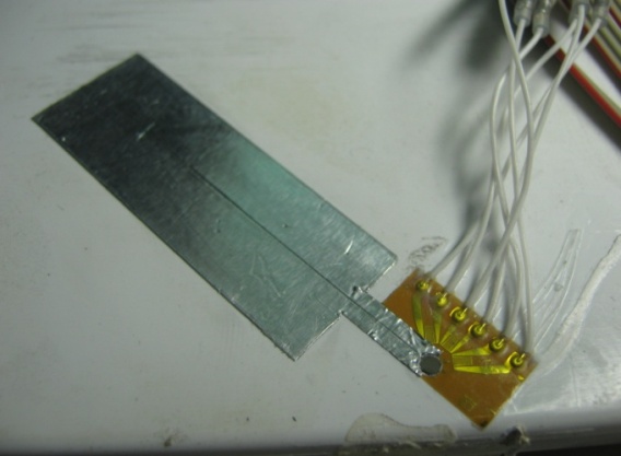
  • Determining “zero” depth manually, stopping the cutter when it begins to produce plastic cuttings (figure 3, left), or
  • Using a special aluminum adhesive tape so that “zero” depth is determined automatically. Once the “zero” point is determined, it is necessary to translate the system by a distance equal to the sum of the thicknesses of the strain gauge rosette and special aluminum tape. (figure 3, right).

4. Determining operating parameters

Measuring residual stresses in plastic materials with the hole-drilling method involves very different aspects from applying the same method to metal materials. In plastic materials the modulus of elasticity is lower and therefore measured strains are much higher, applying the same load, and the material is more sensitive to the operation of removing material. The cutting speed, feed rate, and delay time in acquiring strain readings have to be selected appropriately.

4.1 Speed of rotation during drilling

The drill speed is undoubtedly one of the parameters that most influence the measurement of residual stresses in plastic materials with the hole-drilling method. High-speed drilling with an air turbine, which is the technique normally used for measuring residual stresses in metal materials, cannot be applied as generated heat causes the plastic material to melt and considerably increases the temperature in the areas where the strain gauges are applied.

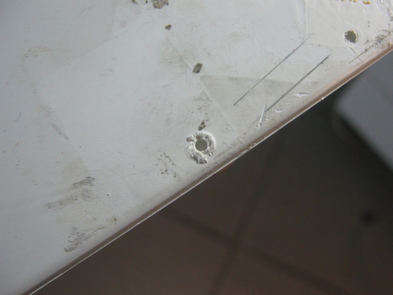
By way of example, figure 4a shows a hole made in plastic material with the high-speed drilling system using an air turbine: melting of the plastic material around the sides of the hole is clearly evident. Lowering the compressed air pressure and the resulting slowing down of the air turbine can only reduce this effect but are certainly not sufficient to eliminate it.

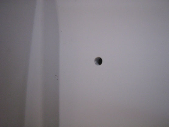
The cutting speed, therefore, has to be very low. In figure 4b one can see the quality of a hole made with the low-speed drilling system (under 200 RPM), designed for measuring residual stresses in plastic materials.

4.2 Feed rate

Since plastic materials are highly sensitive to mechanical stresses, various experimental drilling tests have been conducted to determine the optimal feed rate.

The test results have shown that the drilling tool has to be advanced more slowly in order to reduce the time of instability after drilling. Reducing the feed rate means increasing the time it takes to measure residual stresses: the right compromise between these two aspects has led to determining the optimal speed for drilling holes in plastic materials.

Table 2 shows the time necessary for drilling and the average stabilization time for each feed rate analyzed: the best compromise is achieved with a feed rate of 0.1 mm/min.

4.3 Choice of delay time

The delay times serve to allow strain readings to be acquired when the specimen returns to a state of thermal and mechanical balance after the hole is drilled. Testing has shown that the thermal balance, which is affected by the drilling process, is reached with very few seconds of delay. 

To evaluate the time required to attain the mecanical balance of the component, testing has been necessary to measure the trend of strains throughout the whole stage of drilling the plastic material.

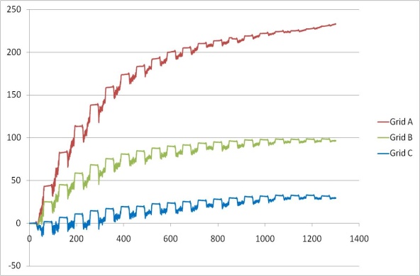
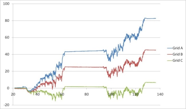
Using a QuantumX amplifier and the catman acquisition software produced by HBM, it has therefore been possible to measure the trend of the strains measured during the entire drilling operation: the results, shown in figure 5, show that the system is mechanically unstable during the drilling process and that it is necessary to wait approx. 90 seconds before the system returns to stability. With a sufficient delay time, the usual strain vs.depth curves can be observed for each strain gauge grid. The curves refer to tests with a feed rate of 0.2 mm/min.

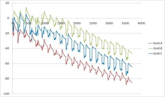
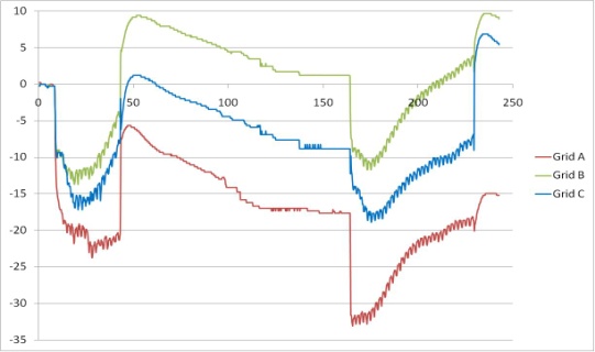
The same experimental tests have been repeated also during the drilling of metal materials (steel and aluminum: the results have shown the behavior of the system but with a faster stabilization time (3-5 seconds). In Figures 6 and 7 it is possible to observe in detail the strain trends in a metal material (Steel) and a plastic material (Polycarbonate).

4.4 Verification of temperature variation on the plastic component

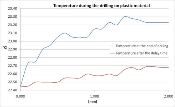
Once the drilling system was designed, the temperature on the plastic (polycarbonate) component during the drilling process was measured. A 2-mm-deep hole was then made and the temperatures on the specimen were acquired with a type K thermocouple installed at the same distance from the hole as the strain gauge grids, positioned opposite grid 2 (or B).

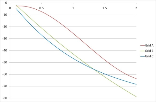
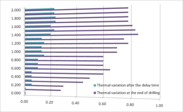
Figure 8 shows temperature versus hole depth. Twenty seconds was set as the delay time between drilling steps and a feed rate of  0.2 mm/min (standard rate for tests on metal materials such as steel) was chosen for the test.

The results demonstrate that the drilling tool does not generate excessive heating at the strain gauge grids. The maximum temperature variation recorded is at the end of the drilling step and is under 1° C.

In addition, during the delay time a rapid reduction of the temperature of the component and return to the initial temperature is observed. In fact, after 20 seconds it may be seen that the temperature attains the initial values: the maximum variation measured in relation to the initial temperature is 0.24°C.

5. Conducted tests and results obtained

A plastic component of a polycarbonate household electrical appliance was tested. A Young’s modulus of 2650 MPa,  a Poisson’s ratio of 0.37 and a tensile strength of 80 MPa were considered for this material.

The following testing conditions were adopted for the automatic measurement system:

  • Maximum depth: 2mm
  • Drilling step: 0.05 mm
  • Number of drilling steps: 40
  • Drilling step trend: linear
  • Feed rate: 0.1 mm/min
  • Delay time: 90 sec.
  • Strain gauge rosette: HBM K-RY61-1.5/120R-3 prewired, 3-wire connection
  • HBM Spider 8.30 strain gauge amplifier

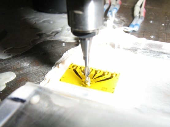
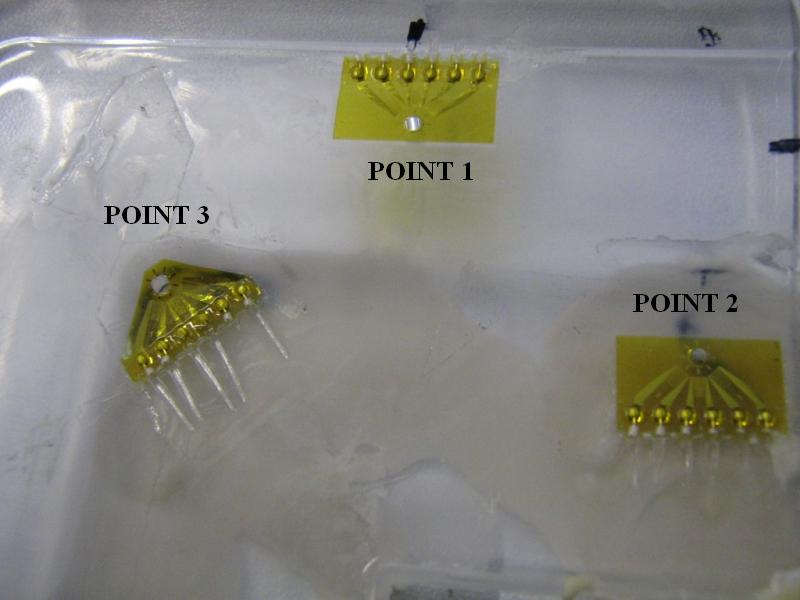
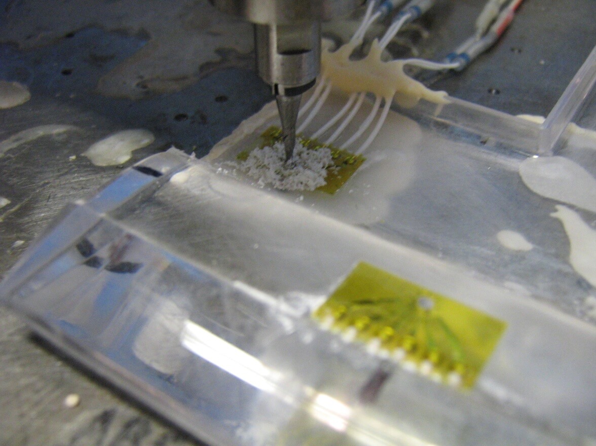
Three measuring points were set up. The positions are shown in figure 9 and two drilling stages can be seen in figure 10.

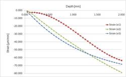
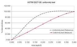
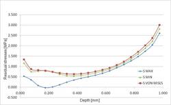
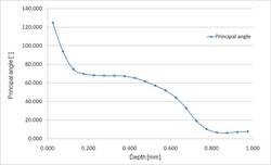
By way of example, figure 11 shows the results obtained for measurement of residual stresses at measuring point 1. The graphs show the trends of the strains, the principal stresses and the alpha angle, which were measured in accordance with the provisions of standard ASTM E837. Similar results were obtained at the other measuring points but are not provided solely for the sake of brevity.


Figure 11a. Strains versusFigure 11b. Uniformity test (ASTM E837-08)
Figure 11c. Principal stresses and ideal stress versus Figure 11d. Alpha angle versus depth.

6. Conclusions

Use of an automatic system for measuring residual stresses in plastic materials has proved indispensable for carrying out reliable measurements on the materials analyzed. In fact, manual drilling or high-speed drilling methods do not allow reliable measurements.

The optimal parameters have been defined for the drilling process and acquisition of strain values in applying the hole-drilling method to injection-molded plastic components. In view of high strain gauge sensitivity to external factors, the remote control of the automatic drilling and data acquisition system has proved extremely effective.