Test Rig for Induction Motor Quasi-Static Electromechanical Characteristic Determination Test Rig for Induction Motor Quasi-Static Electromechanical Characteristic Determination | HBM

Test Rig for Induction Motor Quasi-Static Electromechanical Characteristic Determination

The paper presents a test rig for the determination of the quasi-static electromechanical characteristics of induction motors supplied with sinusoidal voltages. The paper describes in detail the test rig, the used instrumentation, and the characterization tests that can be performed on it.

The motor under test is driven by another speed-controlled motor needing a particular attention from the control point of view. The ‘on-line’ nature of the proposed measurement technique is made possible both by the high dynamic of the electric drive, and the high sampling rate, precision, and accurate synchronization features of the used data-recorder and acquisition system. Examples of quasi-static electromechanical characteristics obtained with the proposed test rig are reported for a 1.5 kW three-phase induction motor and a 0.75 kW permanent-split capacitor-run single phase induction motor.

Introduction

Broadly speaking, the electromechanical characteristics of induction machines show a mechanical quantity as function of an electrical/mechanical one. Among all the possible combinations, the most famous examples of electromechanical characteristics are surely the “torque vs. speed” or the “torque vs. current” ones. An electromechanical characteristic immediately gives a visual sensation of the machine performance and its usefulness is undebatable both from the teaching and applicative point of view [1]. The induction motor electromechanical characteristics can be computed by means of its well-known equivalent circuit assuming more or less sophisticated approaches to take into account the magnetic non linearity, the skin effect in the rotor bars, and stray load losses [2], [3].

On the other hand, the determination of the electromechanical characteristics directly by laboratory tests (in accordance to international standards [4], [5]) can be very time consuming, with a notable human efforts, and quite expensive when the ‘real’ characteristic must be measured. A typical example is the evaluation of the starting torque and maximum torque at the rated voltage, in particular for big induction motors. Due to the installed current/power limitation of the manufacturer laboratory, the direct tests are often performed at reduced voltage. As a consequence, the rated electromechanical characteristic is usually extrapolated considering a squared proportionality between the torque and the supply voltage.

In order to explore the whole torque vs. speed characteristic the acceleration test is usually adopted, where a large inertia is connected as mechanical load for the Motor Under Test (MUT) [6]. With this inertial load, the motor acceleration will be slow enough to validate the quasi-static operation mode all throughout the test. In [2] the authors discuss in detail this test providing the equations to be used for selecting the best inertia to be connected to the motor shaft. It is well evident that the used inertia size is a function of the motor size. In addition, during the acceleration test the total inertia is constant, and the operator cannot change the speed profile after the turn on of main switch that supplies the MUT.

Thanks to the modern electrical drives, the torque vs. speed characteristic can be nowadays determined connecting the induction motor under test with a second machineacting as active brake and called in the following as “Driving Motor” (DM) [7]. In fact, when supplied by a bidirectional converter, the driving motor can be controlled in speed or torque, both in term of amplitude and sign. Typically, a regenerative operation mode is used for the DM to impose the wanted load torque to the shaft of the motor under tests. In this case, the test bench can be used to perform the rated load temperature test and the variable load tests described in [4], but it is not sufficiently adequate to explore the part of the torque characteristic from the starting condition up to the pull out torque.

For this reason, the authors present in this paper a test rig for the measurement of the electromechanical characteristics of induction machines using a speed-controlled DM that imposes the shaft speed with high accuracy and high dynamic from zero up to the synchronous speed. Thanks to the proposed control solution for the DM and the simultaneous record of all the electric and mechanical quantities with impressive sampling rate and precision in each point of the imposed speed profile, the whole machine characterization can be quickly performed. For the considered cases of study, 5-10 seconds were enough to yield very good results. Therefore, the proposed test rig could perform ‘on-line’ validation tests at the end of the production lines, in particular for small and medium size induction motors.

The paper is organized in as follows. The proposed test rig is described in detail in Section II, while the control strategy of the DM is analyzed in Section III. The proposed test rig features are discussed in Sections IV and V, considering as case studies a three-phase induction motor and a permanent-split capacitor-run single phase induction motor, respectively.

Test rig description

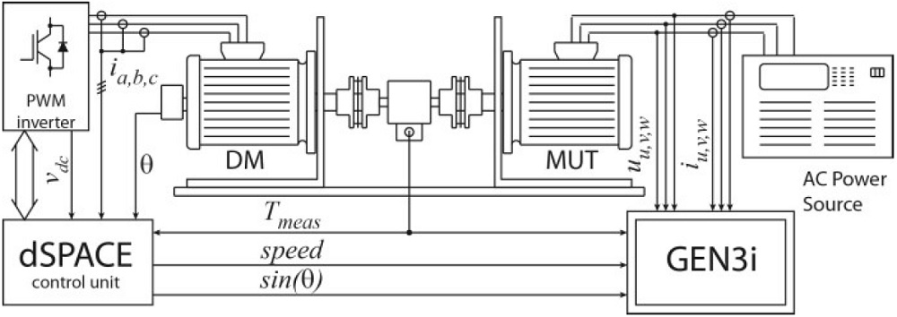
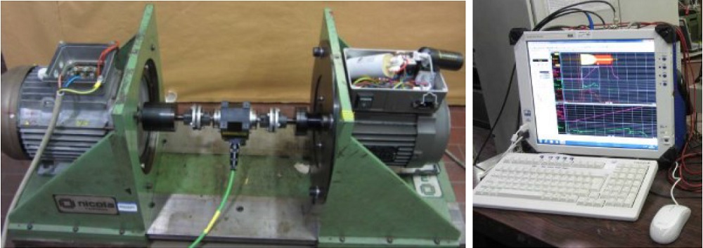
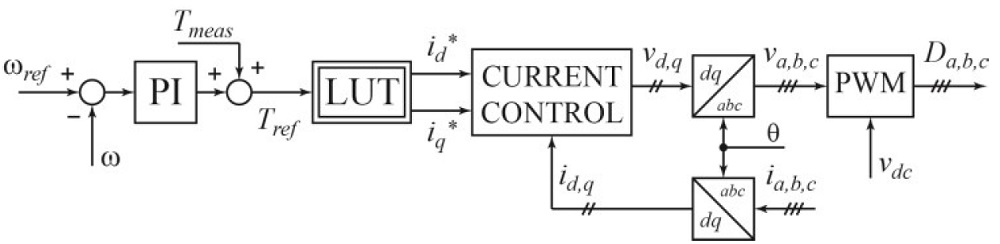
The proposed test rig is quite complex and consists of several parts, as depicted in the schematic block from Fig.1. The MUT and the DM are mounted on mechanical supports using vertical plates and their shafts are coupled together through a torque transducer, as also shown on the left side of Fig.2. The mechanical structure and the couplers must obviously withstand the mechanical stresses produced during the tests. The measured torque signal is recorded for measurement purposes, but it is also provided to the DM speed control system, as described in the next section. The main characteristics of the employed torque meter (Vibrometer TM208) are: rated torque 20 Nm, overload torque 40 Nm, 0.1% accuracy, and bandwidth 1 kHz.

The DM can be any machine able to provide the torque and speed that are needed for the tests. In the proposed test rig, the DM is a 2.2 kW, 14Nm@1500 rpm Synchronous Reluctance (SyncRel) motor fed by a PWM inverter with braking capability. The DM is speed-controlled by means of a dSPACE DS1104 control unit. The motor under tests is supplied by a sinusoidal power source, in order to regulate the voltage during some tests.

The test rig core is the data acquisition system obtained with the HBM GEN3i data-recorder shown in Fig. 2 (right). The GEN3i data-recorder is able to record synchronously 12 insulated channel with 2 MS/s continuous data acquisition. Thanks to the impressive continuous sampling rate and the measurement precision it is possible to record data for long periods without loss any information of short period or transient phenomena.

The measured quantities by the GEN3i data recorder are:

  • MUT phase currents iUVW and voltages uUVW;
  • Shaft torque, speed and a synchronization signal sinϑ (the last two signals are provided by the dSpace system).

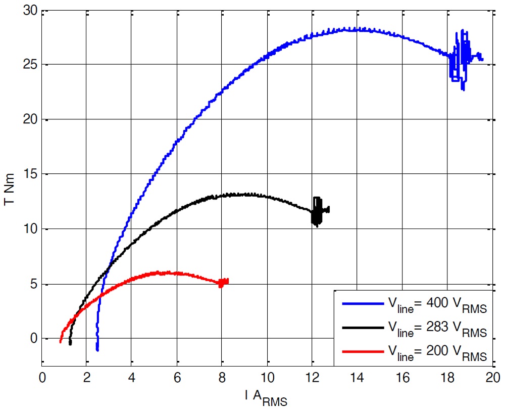
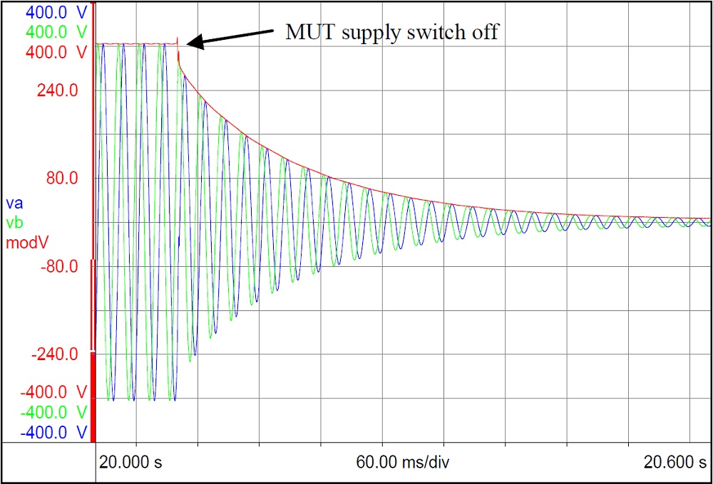
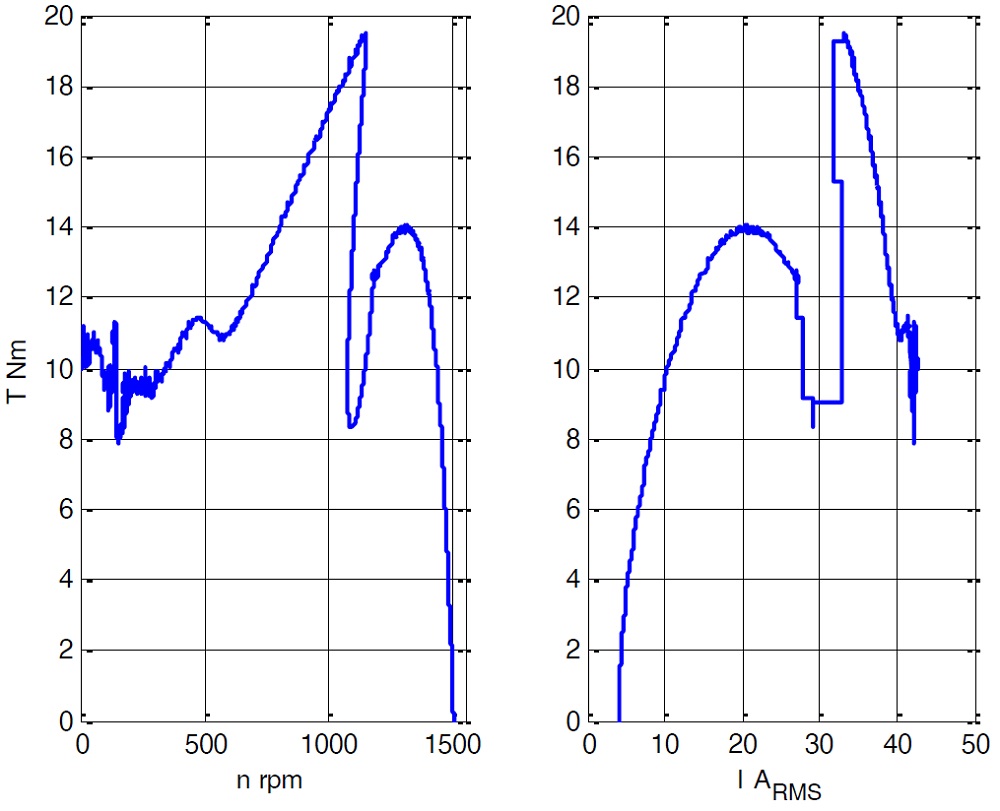
Just to give an example of the features provided by this high speed data acquisition system, some acquired electrical and mechanical quantities that are needed to determine the torque vs. speed characteristic of a three-phase induction motor are shown in Fig.3.

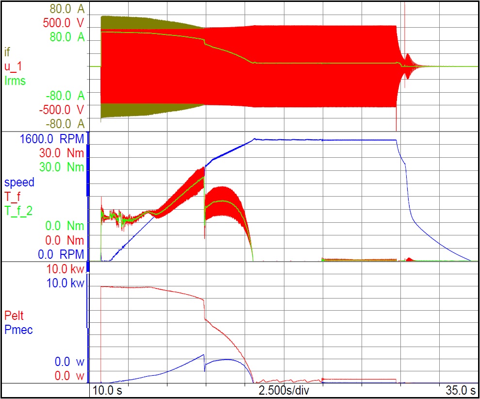
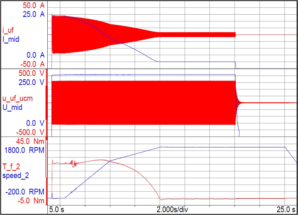
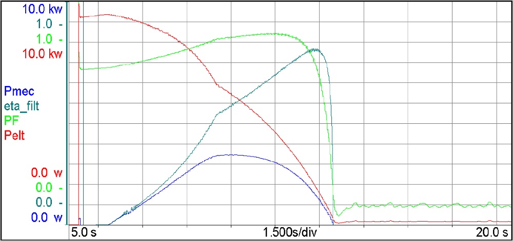
In addition to the high speed acquisition performance, the data recorder provides many functions for data filtering and mathematical computations. Taking into account the amount of data to be managed, these features are mandatory to extract the wanted filtered quantities directly from the acquisition system [8]. As example, some computed quantities during the starting of a three-phase induction motor are reported in Fig.4. To get good results, the high speed acquisition data system must be combined with very good dynamic performance of the DM system used to load the MUT. For this reason, the characteristics and performances of the DM will be presented and discussed in detail in the next section.

Speed control of the driving motor

As already mentioned in the previous section, the DM is a speed-controlled SyncRel motor whose control scheme is shown in Fig. 5.

The speed control loop represents the outer loop of a vector control scheme implemented in the synchronous (d,q) rotor frame. The reference speed is imposed by means of a special speed profile (explained later), while the speed feedback is measured using an encoder having 512 pulses/rev (Fig. 1).

The speed controller is a Proportional-Integral (PI) regulator whose output is added with the measured torque to get a final reference torque Tref in a feedforward fashion. The reference torque is the input of a 2-D Look-Up Table (LUT) whose outputs are the reference d-axis current and the reference q-axis current employed by a standard inner current control scheme implemented in rotor (d,q) frame, as depicted in Fig. 5. The LUT is computed from a magnetic model identification procedure of the DM [9] and obtains a Maximum Torque per Ampere (MTPA) operation of the SyncRel motor.

As depicted in Fig. 5, the current control uses the measured DM phase currents iabc and the measured rotor position ϑ. The inverter DC link voltage vdc is also measured to account for the DC link voltage variations in the computed inverter duty-cycles Dabc.

To get maximum speed loop dynamic performance, the feedforward term represented by the measured torque is mandatory. In addition, the LUT should be as precise as possible to get an accurate torque control through (d,q) current regulation.

Three-phase induction motor testing

The test rig performance has been evaluated by testing a small size three-phase induction motor whose rated parameters are listed in Table I. In the following the different tests performed with the three-phase induction motor are described in detail.

A. Measurement of the quasi-static torque characteristics

The torque characteristics can be easily determined by imposing to the DM speed control scheme a particular reference speed ramp, while the MUT is supplied with the rated voltage. A low value for the speed ramp acceleration is desired to impose a quasi-static operating condition for the MUT, but the ramp time becomes high. At the same time, the ramp time should be limited to avoid an important increase of the MUT temperature during the test.


Power (W)1500
Voltage (V)400
Current (A)3.8
Frequency (Hz)50
Number of poles4
Speed (rpm)1405
Torque (Nm)10.2
Starting torque (Nm)19.8
Peak torque (Nm)26.4

Table 1: Rated data of the tested three-phase induction motor

Therefore, the length of the speed ramp should be chosen as a reasonable compromise between the quasi-static condition and the increase of the MUT temperature during the test. For this reason, the authors adopted a speed profile containing two different sections having two different accelerations, as shown in Fig. 6. In particular, a faster speed ramp has been used from the zero up to a speed value that corresponds to the pull-out torque, while a slower ramp has been defined to reach the synchronous speed. In this way, a better quasi-static condition can be obtained in the stable part of the torque vs. speed characteristic.

It is very important to avoid speed oscillations during the test; this is possible only if the DM speed control dynamic performance is high, as explained in the previous section.

With reference to Fig.6, it should be also noted that the MUT is supplied at the time instant t0 and it is blocked at zero speed by the DM during the time interval Δt1. This time interval allows measuring the ‘real’ starting torque of the machine when the transient phenomena following the supply switch turn-on are extinct.

The torque versus speed and the torque versus current characteristics for three different values of the supply voltage are reported in Fig.7 and Fig.8, respectively.

The three starting tests with different supply voltage have been performed in rapid sequence with the machine at the ambient temperature. From the characteristics reported in Fig.7 and Fig. 8 it is possible to see that the squared proportionality between the torque and the supply voltage is reasonably respected.

B. Locked rotor test

The locked rotor test is one of the standard tests required for the induction motor equivalent circuit parameter determination. With the proposed test rig, this test can be easily performed imposing a speed equal zero to the DM speed control. Since the motor under test is connected to the torque-meter the starting torque at reduced voltage (the locked rotor voltage) can be measured too.

C. No-load test at synchronous speed

This test allows to determine the magnetizing current and the iron losses with an excellent accuracy because the mechanical and windage losses are compensated by the DM. The test is performed by imposing to the DM a mechanical speed equal to the MUT synchronous speed; in this case the MUT slip will be zero. To get a true MUT zero slip, the DM supply frequency must be equal to the supply frequency of the motor under test. This condition can be obtained by linking the output frequency of the drive to the frequency of the main by means of a PLL.

Any other solution which cannot guarantee an isofrequency condition must not be used because a slip not perfectly equal to zero introduces losses in rotor with a wrong evaluation of the iron losses.

D. Efficiency test

The efficiency test is a long duration test used for the determination of the induction motor efficiency [4]. During this test, the DM is used as a brake for imposing the rated torque to the MUT. Thanks the regenerative drive used in the test bench, the shaft power can be recovered in the grid and only the total losses of the system must be provided. At the end of the thermal tests, the drive can be programmed to perform the variable load test, applying the load torque profile imposed by the standard [10]-[12]. The variable load test is required to estimate the stray load losses.

At the end of the rated load temperature tests, the acceleration test can be quickly repeated in order to evaluate the effect of the temperature on the electromechanical characteristics, with respect to the cold condition. For the considered three-phase induction motor the torque variation with the temperature is reported in Fig. 9, for a stator winding temperature of around 25°C and 105 °C (measured at the end of the temperature test), respectively. The performed measurements prove that both in cold and hot conditions the motor provides a starting torque higher than the value declared by the manufacturer (reported in Table I). In hot condition, the pull-out torque design value of the machine is confirmed by the measurements.

It has been also verified that on the torque-speed plane, the working point measured during the rated load temperature test (10.2 Nm @ 1402 rpm) reasonably lays on the torque vs. speed characteristic measured during the starting test in hot condition (10.2 Nm @ 1399 rpm); this results confirming that, thanks to the proposed test rig, it is really possible to estimate quasi-static electromechanical characteristics of induction machines.

E. Test for the rotor time constant evaluation

The rotor time constant is a key parameter for rotor flux estimation in high performance induction motor vector control [13]. This test can be done using the same operating condition of the no-load test at synchronous speed. The DM is speed controlled and imposes zero a slip to the MUT. While the motor under test is running in synchronous condition and it is supplied with its rated voltage, the main switch is turned-off.

The data acquisition system is used to store the voltage at the terminal of the motor under test. This voltage will be equal to the supply voltage when the main switch is in “ON” position, while it will be equal to the stator Electro-Motive Force (EMF) produced by the rotor flux when the main switch is in the “OFF” position. The EMF amplitude will decay as first order system defined by the rotor time constant. The envelopeof the stator EMF waveforms allows evaluating the rotor time constant with an excellent accuracy, because the rotor time constant is evaluated in an electromagnetic condition very close to the operative one. In fact, the time constant computed with this method is not affected by the rotor current skin effects, as happens when it is computed using the rotor parameter values coming from the locked rotor test.

For an accurate estimation of the rotor time constant, the authors used the decay of the stator voltage vector magnitude computed as the square root of the stationary frame (alfa, and beta) stator induced voltage components An example of the data available after performing the rotor time constant evaluation test is reported in Fig.10, where is well evident the decay of the stator EMF amplitude when the main switch is turned off. For the tested motor a rotor time constant equal to 114 ms has been estimated.

F. Standard no-load test

The classical no-load test is again one of the standard tests used for determination of the induction motor equivalent circuit parameters. For this test, the proposed test rig is not necessary because during the test the motor has to be free to rotate without mechanical load connected to the motor shaft.

For performing this test the motor under test has to be just mechanically disconnected from the torque-meter and the DM shaft. The data acquisition system is still used synchronizing the time interval for the measurements with the supply voltage applied to the MUT.

Single-phase induction motor testing

The test rig has been also used to measure the electromechanical characteristics of single phase induction motors. In particular, the tested machines were a permanentsplit capacitor-run single phase motor having the nameplate data reported in Table II.

For the single-phase motors it has been used a speed ramp (0÷1500 rpm) lasting 10 seconds. The measured electrical and mechanical characteristics for this speed ramp are shown in Fig.11, while the torque versus speed and torque versus current characteristics are shown in Fig.12.

During the MUT starting, the capacitance value of the capacitor connected to the secondary winding automatically changes from 490 μF (at starting) to 30 μF (normal working condition).

As expected, the capacitance variation involves changes in the shape of the torque characteristics, as clearly highlighted in Fig. 12; the torque transition is due to the switch from the starting capacitor to the running capacitor. The transition happens for a speed close to the breakdown torque corresponding to the lower capacitance value.

It is important to remark that data acquisition system was able to ‘capture’ this sudden phenomenon without particular problems, providing satisfying results of the performance of the single phase machine in the whole speed range.

Conclusion

The paper presents a test rig for the determination of the quasi-static electromechanical characteristics of induction motors supplied with sinusoidal voltages. Respect to other solutions proposed in the literature, the proposed test rig features the following advantages:

  • The data acquisition is started at zero speed and the MUT is kept at standstill for a true evaluation of the starting torque. This is possible by using a speed-controlled DM featuring very good speed regulation performance.
  • The use of the HBM GEN3i data recorder allows obtaining a complete data stream without synchronization problems that are common to power analyzers. Moreover, the used data logger allows capturing transient phenomena that are difficult, or even impossible, to observe with conventional and power meters. The data is stored and can be subsequently used with special filtering and computation functions to get secondary quantities (efficiency, power factor, power, losses, etc).

The obtained results for the two tested machines are very good. The test rig is able to perform a complete electromechanical characterization of the MUT in less than ten seconds. For this reason, the proposed test rig is a good solution for performing ‘on-line’ validation tests at the end of the production lines, in particular for small and medium size induction motors.

Acknowledgment

The authors are grateful to HBM Italia Srl and HBM Deutschland GmbH for the support provided in the data acquisition system realization.

Politecnico di Torino
Dipartimento Energia
Corso Duca degli Abruzzi 24, 10129 Torino, Italy

Reference

[1] R. Buinac, V. Tomljenovic, “Determination of the torque-speed characteristic of induction motor in electric machinery education”, Conf. Rec IEEE MIPRO’13, 2013, pp. 765-769.
[2] I. Boldea, S. A. Nasar, “The induction Machine Handbook”, CRC Press, ISBN 0-8493-0004-5.
[3] A. Boglietti, A. Cavagnino, , L. Ferraris, M. Lazzari, “Induction Motor Equivalent Circuit Including the Stray Load Losses in the Machine Power Balance”, IEEE Trans. Energy Conversion, Vol. 23, No. 3, Sept. 2008, pp. 796-803.
[4] IEEE Standard, “Test Procedure for Polyphase Induction Motors and Generators” (ANSI), IEEE Std. 112-2004.
[5] IEEE Standard, “Test Procedure for Single-Phase Induction Motors”, IEEE Std 114-201.0.
[6] R. Cipin, M. Patocka, J. Vondrus, “Acceleration method of the IM torque-speed characteristics measurement”, Conf. Rec. IEEE POWERENG’11 , 2011 , pp. 1-5.
[7] “Line Regen Motor Test Dynos”, Baldor technical literature
[8] B. Szabados, J. H. Dableh, R. D. Findlay, G. M. Obermeyer, R. E. Draper, “Measurement of the torque-speed characteristics of induction motors using an improved new digital approach”, IEEE Trans. Energy Conversion, vol. 5, Sep. 1990, pp. 565-571.
[9] E. Armando, I.R. Bojoi, P. Guglielmi, G. Pellegrino and M. Pastorelli, “Experimental Identification of the Magnetic Model of Synchronous Machines”, IEEE Tran. On Ind. Applicat., Vol. 49, Issue 5, 2013, 2116- 2125.
[10] A. Boglietti, A. Cavagnino, S. Vaschetto, “Induction motor EU standards for efficiency evaluation: The scenario after IEC 60034-2-1”, Conf. Rec. IEEE-IECON 2011, 2011, pp, 2786 – 2791.
[11] A. Boglietti, A. Cavagnino, M. Lazzari, M. Pastorelli, “Induction Motor Efficiency Measurements in Accordance to IEEE 112B, IEC 34-2, JEC 37 International Standards”, Conf. Rec. IEEE-IEMDC’03, 2003, ISBN 0-7803-7818-0, pp. 1599-1605.
[12] A. Boglietti, A.Cavagnino, M.Lazzari, M.Pastorelli, “International standards for the Induction Motor Efficiency Evaluation: A Critical Analysis of the Stray-Load Loss Determination”, IEEE Trans. Ind. Applicat., Vol.40, No.5, September/October 2004, pp.1294-1301.
[13] D.W. Novotny and T.A. Lipo, “Vector Control and Dynamics of AC Drives”, Clarendon Press Oxford, 1996.

Politecnico di Turino

Learn more about it

Related Pages