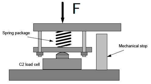
Practice shows that load cells with smaller maximum capacities are often more frequently overloaded than load cells with high maximum capacity ranges. For example, a load cell with a maximum capacity of 20 kg can be significantly damaged simply by a falling wrench.
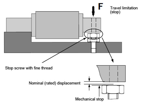
The designer can also realize and implement their own individual overload protection for a series of load cell geometries. Figure 1 shows a design proposal for an overload protection for the HBM load cell type Z6. The possible deflection/travel of the load cell is limited here by a mechanical stop.
The data sheet data nominal (rated) displacement describes the deformation value of the load cell at nominal (rated) loading. The possible travel, dependent on the load cell type and its maximum capacity range, is limited by a mechanical stop to 120 - 150% of the nominal (rated) displacement in order to prevent an overload of the load cell.
The stop is adjusted here with distance gauges. As the described deformations are very low - in practice just several 1/10 mm - fine thread screws that can be tensioned have been proven to be suitable. It is also recommended that the gap between load cell and stop is protected against contamination; because contamination can also be a cause for measurement errors such as unwanted travel limitation.
Displacement different to that specified in the data sheet may arise if the load cell support structure is soft. The overload protection frequently occurs too early because the mounting plate is bending. The gap between load cell and stop must therefore be increased. It is advantageous here for the user to be able to load the weighing device with the maximum capacity and then set the remaining gap to the mechanical stop from 0.05 to 0.1 mm.