Test rig description
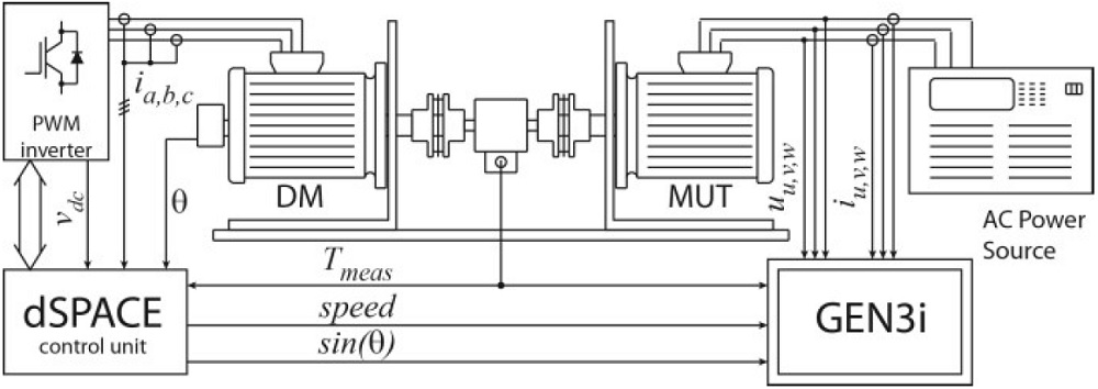
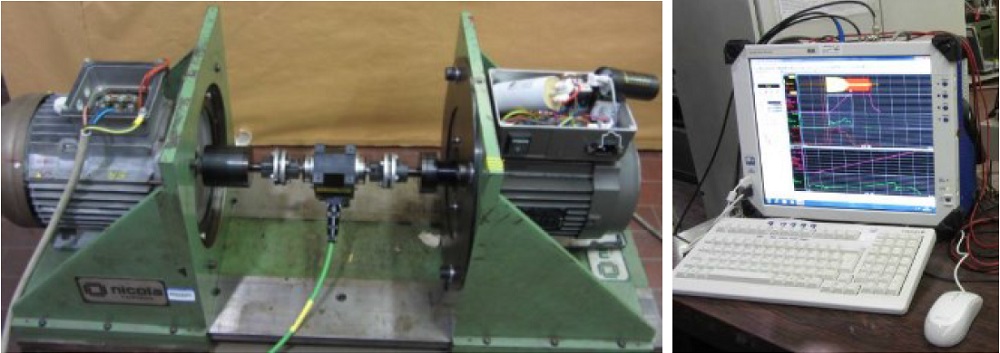
The proposed test rig is quite complex and consists of several parts, as depicted in the schematic block from Fig.1. The MUT and the DM are mounted on mechanical supports using vertical plates and their shafts are coupled together through a torque transducer, as also shown on the left side of Fig.2. The mechanical structure and the couplers must obviously withstand the mechanical stresses produced during the tests. The measured torque signal is recorded for measurement purposes, but it is also provided to the DM speed control system, as described in the next section. The main characteristics of the employed torque meter (Vibrometer TM208) are: rated torque 20 Nm, overload torque 40 Nm, 0.1% accuracy, and bandwidth 1 kHz.
The DM can be any machine able to provide the torque and speed that are needed for the tests. In the proposed test rig, the DM is a 2.2 kW, 14Nm@1500 rpm Synchronous Reluctance (SyncRel) motor fed by a PWM inverter with braking capability. The DM is speed-controlled by means of a dSPACE DS1104 control unit. The motor under tests is supplied by a sinusoidal power source, in order to regulate the voltage during some tests.
The test rig core is the data acquisition system obtained with the HBM GEN3i data-recorder shown in Fig. 2 (right). The GEN3i data-recorder is able to record synchronously 12 insulated channel with 2 MS/s continuous data acquisition. Thanks to the impressive continuous sampling rate and the measurement precision it is possible to record data for long periods without loss any information of short period or transient phenomena.
The measured quantities by the GEN3i data recorder are:
- MUT phase currents iUVW and voltages uUVW;
- Shaft torque, speed and a synchronization signal sinϑ (the last two signals are provided by the dSpace system).
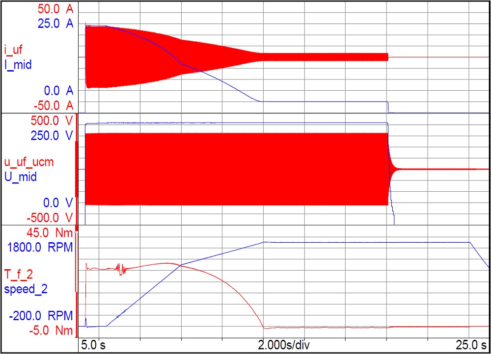
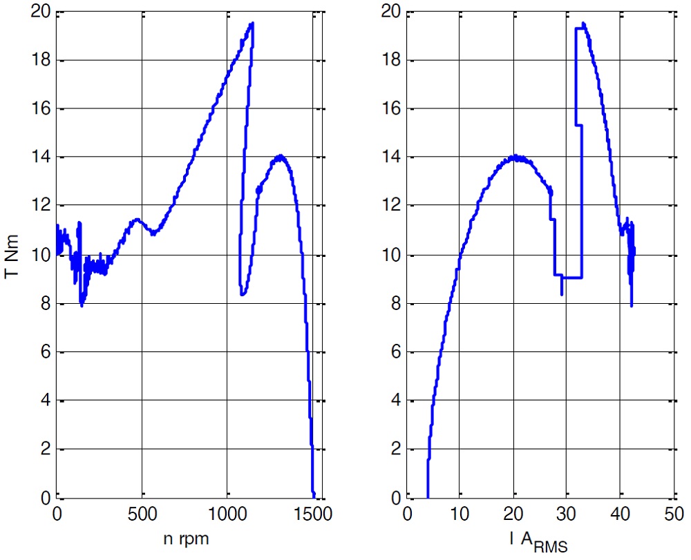
Just to give an example of the features provided by this high speed data acquisition system, some acquired electrical and mechanical quantities that are needed to determine the torque vs. speed characteristic of a three-phase induction motor are shown in Fig.3.
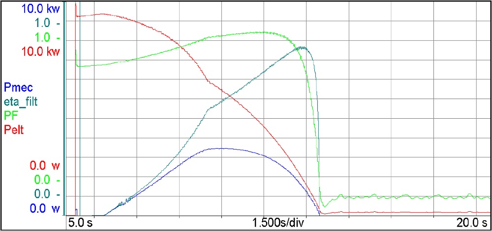
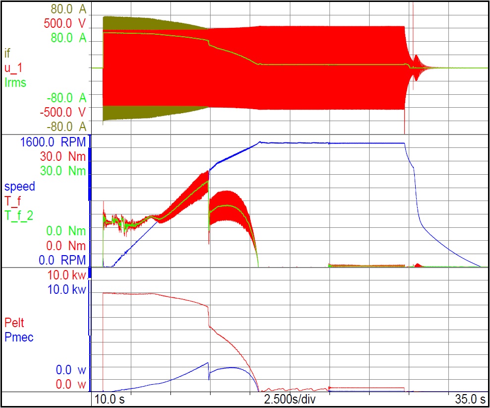
In addition to the high speed acquisition performance, the data recorder provides many functions for data filtering and mathematical computations. Taking into account the amount of data to be managed, these features are mandatory to extract the wanted filtered quantities directly from the acquisition system [8]. As example, some computed quantities during the starting of a three-phase induction motor are reported in Fig.4. To get good results, the high speed acquisition data system must be combined with very good dynamic performance of the DM system used to load the MUT. For this reason, the characteristics and performances of the DM will be presented and discussed in detail in the next section.
