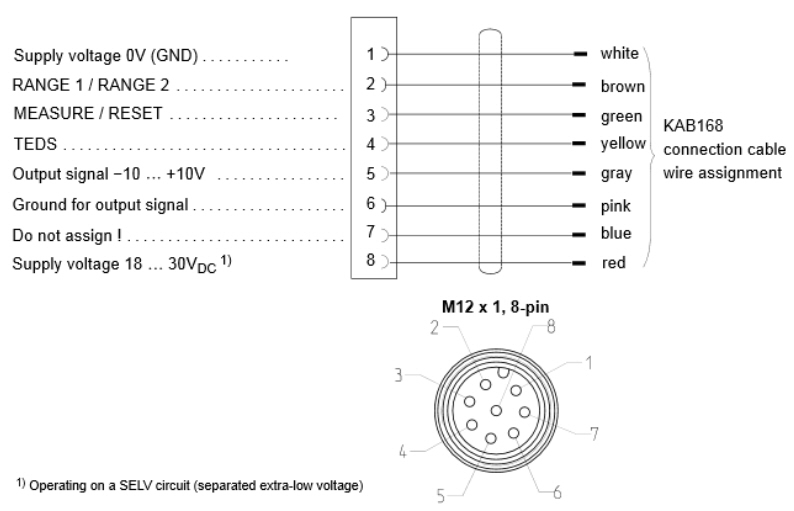
Note: As shown above, the blue wire of the connection cable is not connected.
PMX - Use of a piezoelectric sensor
These tips for use describe how to connect a piezoelectric sensor to a PMX system and a charge amplifier (type CMA/ CMD) and how to put it into operation.
Required equipment
The following equipment is required for implementing the example:
- PMX system (with measuring cards: PX401 and PX878)
- Charge amplifier (in this case: CMA1400)
- 1-KAB168 connection cable (for connecting the charge amplifier to the PMX)
- Piezoelectric sensor
- 1-KAB143 connection cable (sensor connection cable)
Prerequisites
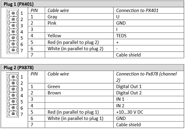
Connecting the cable to the charge amplifier and the PMX requires that the wires of the 1-KAB163 connection cable are combined in two plugs; one of these is connected to the PX401, the other one to the PX878. The pin assignment is as follows:
Cabling with PMX
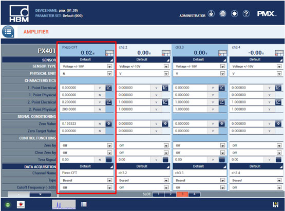
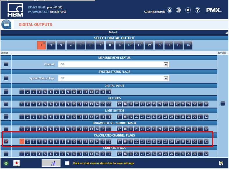
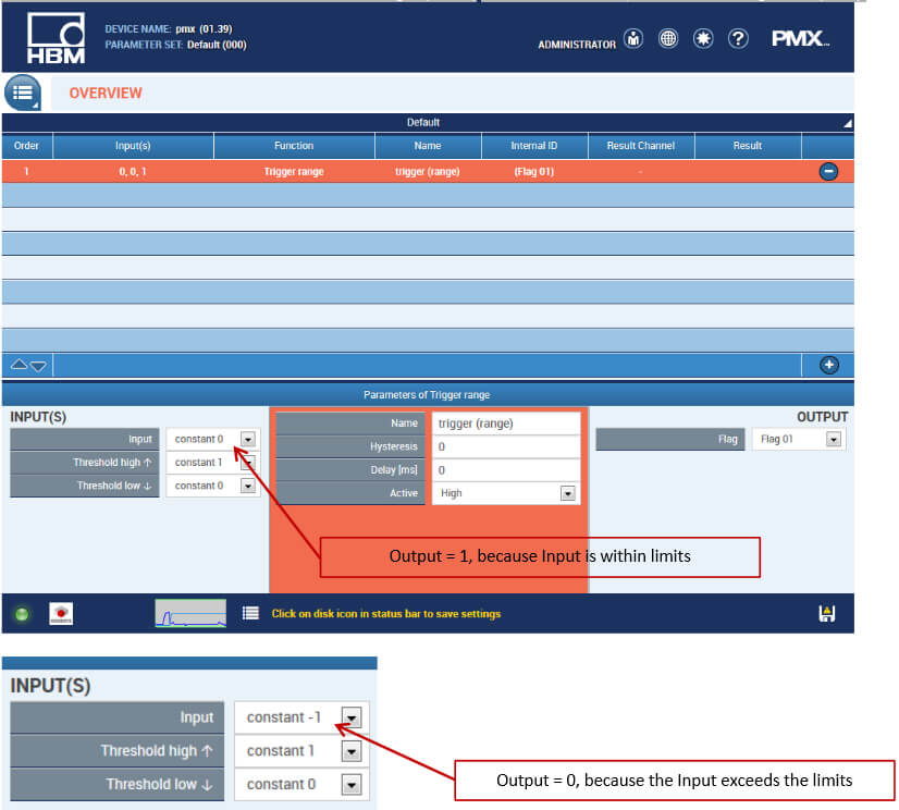
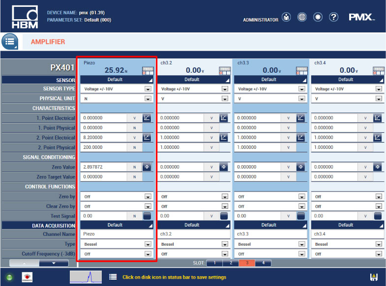
1-KAB143 cable is used to connect the piezoelectric sensor to the charge amplifier. The latter is connected to the PX401 (plug 1) and PX878 (plug 2) measuring cards via the 1-KAB163 cable using the two plugs assembled as described above. The sensor can be put into operation after having been correctly configured
Disclaimer
These examples are for illustrative purposes only. They cannot be used as the basis for any warranty or liability claims
