Signal cables used to connect strain gauge-based sensors to an amplifier module must meet many different requirements. The success of a measurement, just like the reliability of operating machines based on force, also depends on the choice of cable. When planning a setup, it is, therefore, worthwhile considering not only which sensor to choose but also which cable to use – even though, this might seem less important than questions such as how to determine the measurement uncertainty or how to select the right interfaces.
Connection Cables for Strain Gauge Sensors – What to Consider?
What Is the Difference Between Measuring Leads and Standard Power Cables?
To answer this question, let’s start by considering the order of magnitude of the strain gauge sensors’ output voltage.
A strain gauge sensor’s output signal is given in mV/V. HBK offers force sensors that, depending on their design, deliver output signals between 0.5 mV/V and over 4 mV/V when loaded with their nominal (rated) force.
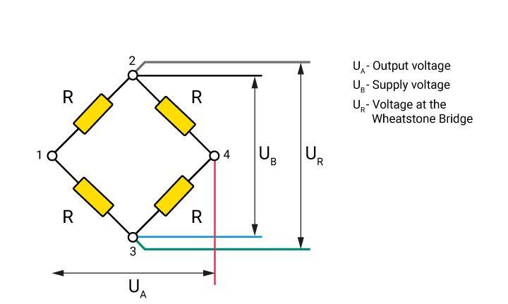
For example, the U10F/250KN has an output signal of 2 mV/V when a force of 250 000 N is applied. Force sensors typically operate with an excitation voltage (supply voltage) of 5 V. This means that at the nominal (rated) force, an output voltage of 10 mV is available, which modern amplifiers can easily resolve into more than 500,000 digits. A digit corresponds to a voltage change of 0.02 µV or 0.5 N. The challenge is to transmit this change from the sensor to the measurement amplifier without loss or interference. Signal cables must, therefore, meet the following requirements:
- Extensive, highly effective shielding to guarantee safety even in critical EMC environments
- Low capacitances and low line resistances. Otherwise, an RC element is created in the cable; this can cause phase shifts and amplitude errors during fast measurements and act as an unwanted filter
- Capacitive symmetry of the wires (the individual pairs of wires need to have identical capacitances) to avoid unwanted influences when using carrier frequency measurement amplifiers
- High geometric symmetry to compensate for electromagnetic and capacitive influences
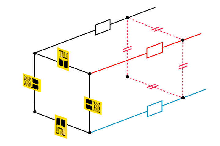
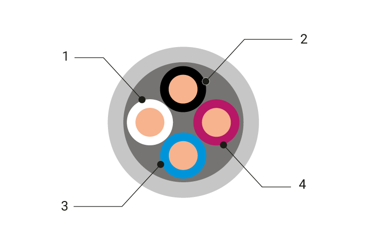
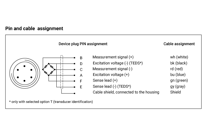
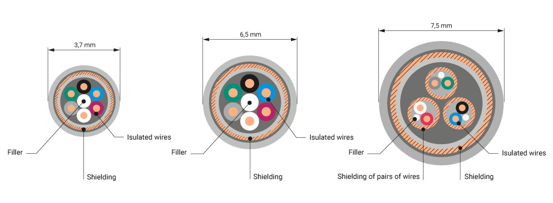
Strain gauge signal cables consist of four (or six) separate wires in each signal cable (see illustrations). The capacitance between the cable wires depends on the design and length of the cable. Ideally, all capacitances are identical and as low as possible. The wire colours correspond to the HBK standard. Blue and black supply the strain gauge circuit with the excitation voltage; the measurement signal is available on the red and white wires, which is amplified and evaluated.
To meet all the above-mentioned requirements, we generally recommend the use of cables that are designed for strain gauge measurements.
Why Are There Different Types of Cable?
The aspects mentioned above cover only some of the requirements for signal cables – that is, the purely metrological prerequisites.
In practice, numerous additional features are required, such as suitability for drag chains, increased temperature resistance, or particularly high measurement accuracy. No cable can meet all these requirements at the same time.
Therefore, HBK’s standard range of force transducer accessories offers three types of cable that cover the various requirements.
The Type 131 cable, which is less than 4 mm thick, is well suited for use in harsh environments, including drag chains. Its small diameter is of great advantage from the mechanical point of view, but it does result in higher capacitances and line resistances. Therefore, this cable cannot be recommended for use with high carrier frequencies (4.8 kHz) in combination with long line lengths. Furthermore, use in very fast measurements is only recommended if the cable is short (less than 10 m).
Type 131 cables can also be used when it is important to ensure the smallest possible force shunt.
Type139B cable has an outer diameter of 7.5 mm. In addition to the shielding that covers the wires of all signal cables, the individual pairs are also shielded, that is, the two wires connecting the force sensor’s output to the measurement amplifier, the two wires carrying the excitation voltage, and the sense lines. This ensures that the excitation currents do not affect the measurement signal or the sense lines.
The cable, with its very low capacitance, is also suitable for high carrier frequencies and very long line lengths (≥ 100 m). It is the first choice for high-precision measurements in the reference range. On the other hand, it is very stiff and has a large bending radius. Type139B cable is, therefore, not suitable for applications where it would be permanently in motion, or for drag chains. This cable is the ‘specialist counterpart’ of the Type 131 cable.
The third type of cable is a compromise between the two previously mentioned specialists: Type157 cables are low-capacitance, have a low line resistance and are less stiff than the double-shielded cable. In addition, they can be used for measurements in higher temperatures.
Detailed technical data for our cables can be found here. All cables are available in different lengths.
In addition to the above, it is important to observe the temperature limits. Chemical influences can also pose a problem. Since it is impossible to test a cable for all kinds of chemicals, only a practical test can lead to the most suitable cable.
The cables mentioned in this article are not suitable for laying in the ground. For these applications – as well as for other applications that raise questions – we recommend that you contact our HBK sales experts and ask them to advise on a solution.
If you intend to solder the plug to the cable yourself, make sure that the shield is extensively connected to ground. With HBK products, the cable shield is galvanically connected to the housing of the force sensor and the housing of the amplifier, creating a Faraday cage for the entire measurement chain. HBK force measurement chains thus achieve a very high level of immunity to electromagnetic interference. Testing in the EMC laboratory and testing according to the IEC standard is part of the type-testing procedure for all HBK force sensors.
Differing electrical potentials in the sensor and amplifier can result in compensating currents in the cable shield, which can strongly interfere with the measurement. The amplifier housing and sensor must, therefore, be shorted at low resistance.
If your application requires very long cables, we recommend the use of extensions – especially when using force transducers with a fixed cable. For this purpose, our cables are also available by the metre, which can be helpful for test benches that are being converted from time to time.