Early warning of damage to wind turbine rotor blades Early warning of damage to wind turbine rotor blades | HBM

Early warning of damage to wind turbine rotor blades

When developing this SHM system, the opportunity arose to use metrology to accompany a realistic fatigue test on a rotor blade test bench. The test comprised several million load cycles in the flapwise direction of the blade and with interruptions, took about 2.5 months. The sensor configuration already outlined was mounted in the blade for this test. Applied were two deflection sensors, to detect the blade displacement amplitudes in the edgewise and flapwise directions, 23 m away from the blade connection, and four fiber-optic strain sensors. These strain sensors were always installed offset by 90° and are stuck in the longitudinal blade direction, in order to detect bending strain. The test objective was to check the measured rotor blade structure for the strain amplitudes at defined locations on the blade, as required by the certification authorities.

A structure like this must be able to withstand the dynamic stress applied to it without damage, over the required number of load cycles. After the official completion of the fatigue test, damage was introduced and the test was re-started. It was possible to detect this damage on the blade metrologically. The test was then interrupted again, the damage repaired and after a structural change, the test was again restarted. The analysis in accordance with the applied methodology, based on the proportionality method, is reproduced in Figs. 11 and 12.

Fig. 11 Progression over time of the proportionality factor of the left-hand sensor (trailing edge)Fig. 12 Progression over time of the proportionality factor of the right-hand sensor (leading edge)

The proportionality factor results determined from the two deflection sensors and the correlating fiber-optic strain sensors are visible there. As the diagrams show, the test was stopped two days after recording began. Shortly before, the two proportionality factors had clearly left their starting level up to the drawn red line, because of the increase in the damage that was introduced. After a short period of shutdown, indicated by the dotted line, the test was again re-started, as marked by 2. During the shutdown period, the damage that had been introduced was repaired, as already mentioned above, and structural changes were made in the transition plate area. The test ended without any more unscheduled interruptions. It is noticeable that after the test was restarted, the proportionality factor levels changed a great deal. The reason for this is the significant structural changes in the area of the transition plate, which have radically altered the dynamic performance of the blade. In addition to this, once the test is restarted, the factors are seen to slowly decrease, which is explained by further, and obviously non-critical structural changes. The proportionality factors must basically be considered over time, as this is the only way to ensure that the change is detectable. The individual values only have limited validity, but cannot logically indicate the development of damage.

Prospects

The evolved measurement technology, comprising deflection sensor, fiber-optic strain gage, data conditioning of the electrical and optical measurement information, radio network connection and batterybacked power supply, is optimized for use in rotor blades. It is useful to install the sensors in pairs, firstly so that ovalization of the cross-section can be detected and secondly, to form a redundant system, which improves the reliability of the status analysis. The simulated results and the real data measured on a rotor blade test bench, show that the sensor technology and methodology have potential as a damage early warning and monitoring system for rotor blades. This system will soon be installed and working in a rotor blade of an operating wind turbine for the first time. The partners involved are confident that this product will be marketable in the foreseeable future.

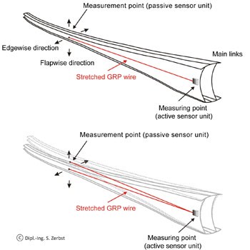
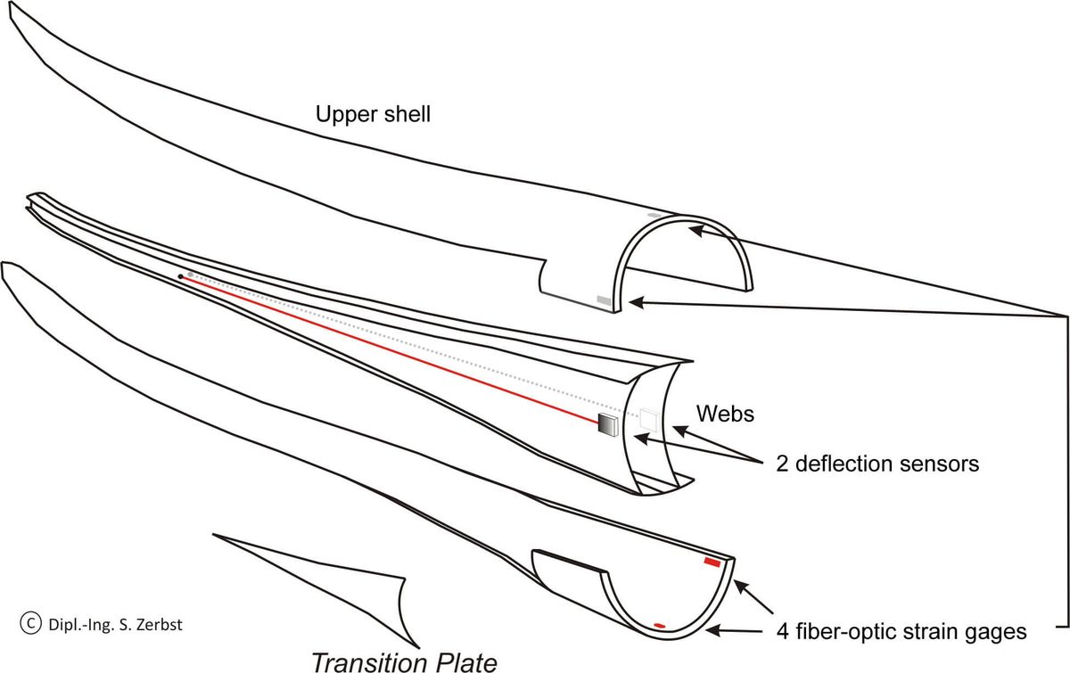
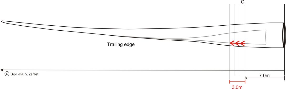
Suitable sensor technology must be employed to detect the damage to wind turbine rotor blades early enough, and minimize the economic consequences.

The sensors must be able to withstand tough ambient conditions and must themselves be readily available. The evaluation methods that supplement this technology must firstly detect damage in the important areas of the structure as quickly as possible and secondly, display it clearly. These structural health monitoring systems (SHM) must not make mistakes, otherwise they do not serve their purpose.

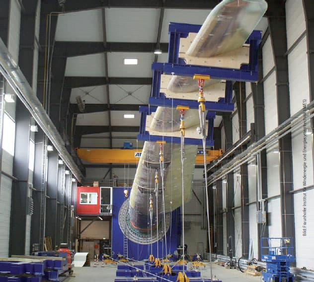
The rapid development of wind energy in Germany in recent years has meant that the Federal German Government objectives of satisfying up to 30% of the country’s energy requirement from renewable energy sources by 2020, are moving within reach. The rotor blades of wind turbines are already more than 60 meters long, and are the key components of wind turbine performance. The design of smaller blades is also continually being optimized, in order to save cost and further improve efficiency. It is still the case that there is very little automation in the production of wind turbine rotor blades, and only some of the manufacturing inaccuracies and deviations from the specification can ever be identified once the rotor blade is manufactured. In the history of wind power right up to the present day, there have been individual cases of rotor blades in the field suffering structural damage that can be traced back to manufacturing faults not previously detected. Suitable sensor technology must be employed to detect the damage early enough, and minimize the economic consequences. The sensors must be able to withstand demanding ambient conditions and must themselves be readily available. The evaluation methods that supplement this technology must firstly detect damage in the important areas of the structure as quickly as possible and secondly, display it without ambiguity. These structural health monitoring systems (SHM) must not make mistakes, otherwise they are useless, as they do not serve their purpose.

New measurement technology for rotor blades

The measurement technology used in rotor blades has to satisfy many requirements. Vast temperature and humidity differences over short periods of time, extreme dynamic and mechanical stress on the sensors and an environment susceptible to lightning strike are the basic demands on the technology. Despite these difficult conditions, minimal uncertainty over a long period of availability is taken for granted.

Deflection sensor

A specially developed deflection sensor seems to be suitable for use in rotor blades and long, extended structures. This sensor is designed to be totally impervious to lightning strikes which, even if they do not actually damage the structure, usually destroy the sensor technology mounted in the rotor blade. The sensor, which can either be installed during blade manufacture or subsequently mounted into the blade, uses the principle of operation shown in
Fig. 1: A special, glass-fiber reinforced plastic (GRP) wire is stretched between the two fastening points. One fastening point resides inside the blade and forms the actual “measurement point” (passive sensor unit). The other fastening point is located at the root of the blade and forms the “measuring point”, the active sensor unit. Fig. 1 shows that the main link of the blade is ideal for deflection sensor installation. The movement amplitude of the blade in the “measurement point” area changes the angle of the GRP wire at the active sensor unit.

This change in angle is converted to a deflection signal by two force transducers in an orthogonal arrangement [1]. The system is outlined in Fig. 2. The sensitivity of the sensor is defined by the tension of the wire, which is kept constant with the aid of a mechanical spring. GRP patches are laminated to the link, and the sensor is attached to these both at the passive and active ends, as shown in Figs. 3 and 4.

Fig. 3 Active sensor unit of the deflection sensorFig. 4 Fastening point in the blade (measurement point)

The active unit is so tightly sealed in the rotor hub area, that it is given adequate lightning protection. All the sensor components further on in the blade are non-metallic and therefore not at risk. If the distance between the active and the passive sensor unit is 20 m and the tension of the wire is a constant 300 N, the following are the relevant characteristic values for the deflection


Fig. 5 HBM deflection sensor with measurement electronics installed
 
  • Non-linearity: < 0.1%
  • Temperature coefficient of transducer
  • zero signal (TK0): < 3*10-5/K
  • Temperature coefficient of transducer
  • sensitivity (TKC): < 3*10-5/K
  • Sensitivity: 20 μm at 20 m sensor length
  • Measuring range: ±200 mm
  • Resolution: 1:104.
 

The transducer evaluation electronics also satisfy demands for ultra-long-term stability, and have a corresponding level of protection with regard to EMC immunity. As can be seen in Fig. 3, these components are mounted directly in the deflection sensor. Signal coupling between the digital transducer electronics and the radio data communication system uses a digital interface, and complies with the latest standards.

Strain sensor technology

In the application described here, the second input quantity for assessing structural integrity is strain, or derived from this, mechanical stress. Strain gages (SG) have been an indispensable tool for this type of experimental stress analysis for decades.

Fiber-optic strain gages are eminently suitable for use in fiber-composite rotor blades because compared to electrical strain gages, their immunity to EMC or the effects of high voltage has far better fatigue strength and durability for counteracting the level of strain and the number of load cycles (damage accumulation) in the rotor blades.

Enormous technological advances in fiber-optic technology, driven in particular by telecommunication needs, also put the focus of attention on optical sensor applications with microstructured areas. So-called Bragg gratings, areas with periodic fluctuations of the optical index of refraction in the core of the crystal fiber, change their wavelength properties when they are affected by external loading [3]. This is shown in diagrammatic form in Fig. 6. The Bragg grating used for measurement changes the wavelength of the spectrum reflected at the grating, as a result of strain.

Fig. 7 Optical linear strain gage and optical rosette

Because the optical fibers are also simultaneously acting as a sensor element and a transmission medium for sensor signals, additional advantages accrue for the user with regard to installation expenditure, robustness and reliability. Commercially available optical strain gages are shown in Fig. 7 [4].

The SHM system described below uses a sensor network of eight fiber-optic strain sensors (4 temperature compensators) and two deflection sensors. A hybrid measurement system [5] connected under the master-slave principle to a network station by a packet radio system, is used for signal analysis. This makes it possible to use an Internet connection for a multi-valued analysis of measurement data.

Intelligent methodology for an early warning of damage

The performance requirements for the methodology of a damage early warning or monitoring system are no less demanding, compared with the requirements for the measurement technology being used. Basically, there must be no false alarms. It is not economically viable to be shut down because of repair or maintenance work, and this should be avoided. The system must also give the operator sufficient time to react to damage. This means that the damage must be detected early enough, and its potential threat determined. It must be possible to conclude whether the turbine should be shut down immediately, or whether there is still time available for monitoring. The approach to damage early warning presented here involves a global SHM method.

"Compared to electrical strain gages, fiber-optic strain gages have far better fatigue strength." Dipl.-Ing. Stephan Zerbst is a Scientific Assistant and Coordinator of the Services & Measurement Techniques department at the Institute of Structural Analysis (ISD) of Leibniz University in Hanover.

This means that the entire rotor blade in monitored by a minimum number of sensors, in order to detect the global status of the structure. The sensors no longer work as hotspot-monitors, but are viewed together, as a group [7, 8]. The “proportionality method” comes into play here. This is a method that makes use of the proportionality of the maximum vibration rate and maximum dynamic strain or stress during natural vibration [6].


These two correlating measurands are detected and compared, subject to the direction of natural vibration that is excited at defined locations on the blade structure. In this case, the vibration rate amplitude is differentiated from the deflection signal. The reference status of the undamaged structure with reference factor “pSystem” that was detected in the beginning is subsequently always compared with a newly determined “pSystem” proportionality factor. If the observed proportionality factor is permanently away from its starting level, this indicates the commencement of damage. The “pSystem” proportionality factor is a system factor that includes all the properties of the structure, such as its material properties, storage conditions, cross-sectional shape, etc. This factor is thus an excellent choice as a damage indicator.

Numerical simulation with damage application

The numerical model of a current rotor blade type was subjected to the various typical damage scenarios that can arise during fatigue testing. As before, failure of the adhesive joints is a highly probable accident that can occur as a result of extreme loading over long periods of time. The basic structure of many modern rotor blades shows that so-called blind adhesive joints are the places where the potential for damage is at its highest. These are, for example, certain adhesive joints on the links, the quality of which cannot be adequately tested during assembly, because of their position. But the joints of the upper and lower shell can also fail under high dynamic loading. Damage was incorporated into the numerical model of a rotor blade, to be detected with a virtual sensor configuration like the one actually mounted in the accompanying realistic test.

Simulated here is the deployment of two deflection sensors mounted along the two main links, and four fiber-optic strain sensors, which record the longitudinal strains in the root area of the blade, 90°apart (see Fig. 8).

The joints of the trailing edge are particularly complex in the so-called transition plate area. This component must be used here to effect a transition between the cylindrical shape of the blade connection to the hub, and the aerodynamic shape of the rotor blade.

“Joint failure” damage is implemented by selecting two coincident series of shell elements in the model and changing their properties. The properties of the damaged element primarily include a greatly reduced modulus of elasticity. In the following, joint failure on the training edge of the rotor blade was incorporated above the transition plate (Fig. 9). This damage starts 7 m away from the hub, at a length of 1 m and increases to 3 m. Excitation of the blade occurs separately, as with the actual fatigue testing, in the edgewise and flapwise directions.

Fig. 10 shows the changes of the two proportionality factors as a result of the increasing damage. Two deflection sensors of different lengths are simulated here, in order to establish how far in the rotor blade the measurement point has to be placed. The optimum location has proven to be situated at about 2/3 of the blade length.

It can be seen that the increasing damage on the trailing edge when considering a movement in the flapwise direction of the blade generates far more pronounced changes of the proportionality factors than the observation of the edgewise direction. It is also noticeable that the change to the natural frequency of the particular direction is hardly worth mentioning. This means that the proportionality method responds far more sensitively to the structural changes on the rotor blade than the natural frequency.

The authors:

Dr. Karl-Heinz Haase is the Product and Application Manager at HBM, Hottinger Baldwin Messtechnik GmbH, in Darmstadt.

Dipl.-Ing. Stephan Zerbst is a Scientific Assistant and Coordinator of the Services & Measurement Techniques department at the Institute of Structural Analysis (ISD) of Leibniz University in Hanover,

Dr.-Ing. Martin Knops is Divisional Manager for Rotor Blade Development at REpower Systems AG in Osterrönfeld,

Prof. Dr.-Ing. habil. Raimund Rolfes is the Managing Director of the Institute of Structural Analysis (ISD) at Leibniz University in Hanover.

Wind Turbine Testing with HBM

Opto-electrical interrogators

References

[1] Patent pending PCT/EP 2008/000942
[2] Hoffmann, K.: "Eine Einführung in die Technik des Messens mit Dehnungsmessstreifen" (An introduction to measurement using strain gages) Hottinger Baldwin Messtechnik, Darmstadt.
[3] VDI/VDE/GESA 2660: Experimentelle Strukturanalyse; optischer Dehnungssensor, basierend auf Faser-Bragg-Gitter. Grundlagen sowie Kenngrößen und deren Prüfung (Experimental structural analysis; optical strain sensor, based on a fiber Bragg grating. Basics, characteristic quantities and their testing).
[4] Hottinger Baldwin Messtechnik GmbH product catalog. Experimental stress analysis.
[5] Haase, K.-H.: AIAS – Associazione Italiana per l‘analisi delle sollecitazioni XXXVIII Convegno nazionale, 2009, Politenico di Torino: Benefits of Using Fiber Optics Strain Gages in Experimental Stress Analysis.
[6] Gasch, R.: Eignung der Schwingungsmessung zur Ermittlung der dynamischen Beanspruchung in Bauteilen, Berlin 1968 (Suitability of vibration measurement for determining dynamic stress in structural elements).
[7] Zerbst, S.; Haake, G.; Reetz, J.; Lynch, J.; Rolfes, R.: Integral SHM-System for Offshore Wind Turbines using Smart Wireless Sensors, Proceedings of the 6th International Workshop of Structural Health Monitoring 2007, Volume 2, p. 1889-1896, San Francisco, Sept. 11-14, 2007.
[8] R. A. Swartz, J. P. Lynch, B. Sweetman, R. Rolfes and S. Zerbst: Structural Monitoring of Wind Turbines using Wireless Sensor Networks, Smart Structures and Systems 6, pp. 183-196, 2010.

Acknowledgements

The authors are grateful to the Bundesministerium für Umwelt und Reaktorsicherheit (BMU) (Federal Environment Ministry), and Projektträger Jülich (PTJ ) (Jülich Project Management) for their support in a combined research project.