DB Systemtechnik: Measurement technology in railway engineering DB Systemtechnik: Measurement technology in railway engineering | HBM

Measurement technology in railway engineering

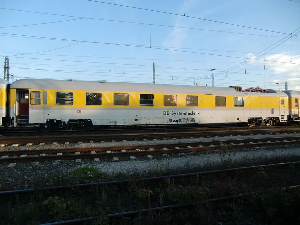
Extensive testing is required for approval of railway vehicles. This includes complex test runs to measure, for example, the forces between wheel and rail, acceleration in the spring stages or relative displacements of moving components. The European Dynotrain research project investigates to what extent computer simulations will be able to replace part of the measurement runs in future. The objective is to facilitate and accelerate European approval procedures. The driving technology division (Prüfungen Fahrtechnik) of DB Systemtechnik, located in Minden, Germany, uses HBM measurement technology for the measurements required for verification of the simulation programs.

Rail traffic is among the safest modes of transport in Europe. The criteria for approval of new railway vehicles are correspondingly strict. The approval procedure requires many conformity checks to be carried through. Measurement runs are mandatory to comply with relevant European standards. The objective of Dynotrain, a European research project involving a total of 21 research institutes and companies from six countries throughout the European Union, is to create a technical basis for facilitating and accelerating the approval procedures for railway vehicles in the future. To achieve this aim, part of the conformity checks required so far that involve relatively complex measurement runs are to be replaced by simulations. First of all, the reliability of these computer simulations, however, needs to be verified by comparison with the results of measurement runs (validation of computer models). Deutsche Bahn AG, with its subsidiary DB Systemtechnik, is a partner to the Dynotrain research project.

Independent testing laboratory

DB Systemtechnik in Minden offers a wide range of engineering services for the rail engineering industry. The division the will operate independently as a wholly owned subsidiary of DB AG from mid 2011, has its main facilities in Minden, Munich and Kirchmöser and employs around 600 staff who make their expertise in the area of railway technology available both to Deutsche Bahn AG internally and external customers. Many years of experience and unparalleled system know-how have made DB Systemtechnik Europe's leading competence center for the rail engineering industry.

DB Systemtechnik performs a wide range of vehicle and component tests in the business segment of approval management, testing and certification; these tests make an important contribution to safe, reliable and efficient rail operations. The DB Systemtechnik test center and expert organization are registered as an associated partner of the Notified Body for interoperability (Assoziierter Partner der benannten Stelle Interoperabilität) at the German Federal Railway Authority (EBA). The total of 18 testing laboratories has been accredited per DIN EN ISO/IEC 17025:2000. About 40 members of staff have been appointed as certified experts by the German Federal Railway Authority.

Measured quantities for the approval of railway vehicles

Wheel-rail forces are among the important measured quantities for the approval of railway vehicles. It is essential to measure these forces during operation; this requires the use of measuring wheelsets. Both the vertical and lateral force component need to be determined. DB Systemtechnik has developed special, strain-gage based measuring wheelsets for these measurements. The forces acting between wheel and rail cause deformation of the wheels and wheelset shaft, which is measured by the strain gages. Based on the interdependencies between force and resulting strain determined by an elaborate calibration procedure, complex software is used for online conversion into the force components Q (wheel-rail contact force), Y (constraining force in the curve) and Tx (forces in the longitudinal direction resulting from braking and starting torque as well as differences in rolling radius).

At the Minden test center, strain gages are installed on the bright metal wheelsets converting them into precise test and measurement equipment. Depending on the geometric characteristics of wheels and shaft, two major methods of measurement are available - one taking into account the wheels and shaft as strain gage installation points, the other one using the strain data from the wheels exclusively. Both methods of measurement involve installation of up to 96 strain gages on the wheelset and their connection in full-bridge configuration. Signal lines are led into the hollow axle through a hole. The complete electronics including amplifiers and signal transmission is located at the end of the axle. When the strain gages, the signal lines and the electronics have been installed, the measuring wheelset needs to be calibrated. For this purpose, the complete wheelset is integrated into a specially developed test bench. It enables both vertically and horizontally precisely defined forces to be applied to the wheels without mutual interference and the response of the full bridges to be determined.

Another important means of acquiring measurement data for analyzing dynamic vehicle characteristics are accelerometers installed on the levels of the unsprung masses (mainly the wheelset) and - if available - the first spring stage and the second spring stage. They measure the accelerations occurring on these levels in lateral, vertical as well as longitudinal direction and, depending on the spring stage, in different frequency ranges.

Relative displacements form the third major group of measured quantities. In general, they only play a subordinate role in the approval of vehicles, however, they often are considered indicators for understanding specific vehicle characteristics. The Dynotrain project expressly chose to use them as major quantities to enable the simulation models of the vehicles under test to be compared with the measurement results taking into account the incorporated test variations.

Last but not least, there is the group of measured quantities describing the track. The following values were continuously recorded:

  • Longitudinal profile (every 16 cm)

  • Track alignment (every 16 cm)

  • Super elevation (every 16 cm)

  • Track gage (every 25 cm)

  • Track cross profile left/right (every 25 cm).

Extensive technology for a complete Dynotrain measuring train

The vehicles under test within the scope of the Dynotrain project included a locomotive, three freight cars and one passenger car, complemented by the DB Netz AG Railab for recording of the track geometry and by a measuring car accommodating the central measurement technology components and the measurement team. These cars were coupled with six additional cars to ensure correct braking behavior. This train configuration - complemented by a traction locomotive for the respective power networks in Switzerland, France and Italy - was up to 400 m long.

Ten of the above described measuring wheelsets were used in the five measuring cars. Over 300 physical channels needed to be recorded and, because of partly differing filter configurations, about 1,000 measurement channels needed to be saved together with all acceleration and displacement signals, track geometry signals and additional information about temperature, air pressure and humidity, GPS data and braking pressure. This places tremendous demands on the measurement system, taking into account the sampling rates of up to 1,200 Hz. In the process, part of the CPU load is already being swapped out. Each of the five measuring wheelset computers computes the total of 48 strain gage full bridge signals provided by two measuring wheelsets up to 1,000 times per second providing the wheel-rail forces that are digitally transferred to the MGC amplifier. The complex fiber-optic network of insularly installed MGC amplifiers and measuring wheelset computers as well as powerful mainframe computers and memories has been specifically designed to withstand such loads. Measurement-data statistics are determined online and can be visualized and subsequently analyzed immediately upon completion of the measurement run. Online recorders visualize part of the raw data to enable the engineer on board to monitor limit values in critical situations. Far more than 3,000 GByte of measurement data have been acquired and saved over about four weeks of measurement runs. They are presently available to the project partners via a fast server connection.

A total of seven MGC amplifier systems was used; they are outstanding for their high flexibility and ease of use. The MGCplus system is suited to many different measurement tasks thanks to its modular structure. Corresponding modules are available from stock for virtually all common transducer types. The Transducer Electronic Data Sheet (TEDS) enables a measurement system to be quickly and easily configured. The amplifiers automatically identify the transducers that are connected; no complex manual configuration is required.
Another advantage of the MGCplus system was of importance to its use in the DB Systemtechnik measuring train: All channels of a measurement system can be recorded absolutely synchronously. This is particularly important in this application, because all measured quantities need to be correlated in subsequent analyses. The stage of data analysis has now begun and will require ongoing commitment on the part of the project partners for two to three years. The data obtained from this project will form a basis for vehicle development, design and approval as well as subsequent research projects for many years.