Effective power can be very easily measured at the generator output. The measurement required for determining the efficiency of a system is significantly more difficult. Determining the fuel mass flow is a widely used method for this purpose. However, directly measuring the mass flow is relatively inaccurate, because several parameters that cannot be easily influenced as well as the type of fuel strongly affect the uncertainty of measurement. In practice, the mass flow of the fuel is indirectly established with the help of previously determined calibration values and simulation programs.
The use of torque flanges in power generation plants
The world's steadily growing energy needs combined with increasing requirements on power generation plants in terms of economical use of resources and protection of the environment demand innovative technologies for running such systems.
Power and efficiency are the two values that are crucial to power generation plants. Efficiency is the ratio between the effective power generated by the generator within a specific time and the drive power supplied to the drive in the form of fuel.
Determining the fuel mass flow
Measuring the input shaft torsion
Another method for determining drive power is to measure torque in the shaft train between drive side and generator which is used, together with the rotational speed, to compute drive power. This is done by measuring the input shaft torsion generated by torque on the driven side. There are several methods available which have in common that torque is not directly determined but indirectly via a torque-related parameter and subsequent calculation. The parameters to be considered in this calculation (e.g. material, shaft geometry) are subject to tolerances which ultimately lead to a relatively large uncertainty in the torque parameter.
Measuring the input shaft torsion via the surface strain
Measuring the input shaft torsion via the surface strain is quite good a compromise. Strain gages are glued onto the shaft for this purpose, then connected into a measuring bridge. The measuring bridge excitation voltage and the measurement signal are transferred contactless via a telemetry system from a stator to the rotating shaft and vice versa. Depending on the installation quality and the components used, this method provides very precise strain measurement values. However, the subsequently calculated value for torque has an uncertainty of approx. 3 to 5% because of the previously mentioned tolerances of the parameters to be taken into consideration. The method has numerous advantages - for example, existing systems can be retrofitted at any time with this system. The achievable uncertainty for the torque parameter is, however, no longer sufficient for the current requirements set for new plants.
Calibrating the shaft train directly for the parameter torque
The uncertainty of the above described methods can nevertheless be decisively improved by calibrating the shaft train or parts of it directly for the parameter torque. The part being calibrated is incrementally loaded in a calibration machine with defined torques and the corresponding output signal is measured and documented. Calibration can be performed on site; however, this may cause problems resulting from both the complex and time-consuming load application and local conditions. Calibration in a calibration laboratory ensures optimum conditions and high accuracy; however, it requires complex and, possibly, changing loading fittings for installing the part to be calibrated in the calibration machine. In addition, in some cases there may not be any suitable calibration machine available due to the dimensions of the component to be calibrated or the maximum torque.
Integration of measurement technology into the drive train
The difficulties described can be avoided relatively easily by considering torque measurement in the drive train already when planning the system. What is needed is a component that is mounted directly into the drive train and rotates with it or even takes over the function of the drive train. This component is already calibrated to the required torque and appropriately certified. It can be easily installed, removed, replaced and recalibrated.
Figure 1 shows a torque flange that is available as a standard version up to 300 kNm and which can also be delivered with a nominal measuring range of up to several MNm. The measurement flange is available as a non-rotating version for measuring reaction torque or as a reference transducer, and as a rotating version with a telemetry system.
Fig. 1: Special features of a torque flange
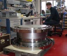 |  |
| Fig. 2: Measuring body of a 2 MNm torque flange | Fig. 3: Installation of a torque flange in a generator set |
Depending on the telemetry system type, the torque flange provides the dynamic torque signal in high quality up to a bandwidth of 6 kHz. This results in the following advantages for the operation of plants for power generation:
- Constantly accurate efficiency measurements (monitoring)
- Fuel consumption analysis and optimization
- Torsion vibration analysis possible without additional sensors
- Identification of variations in the characteristic torque behavior
> Conclusions for repairs or adaptation of service intervals - Short signal time > Fast control and overload protection
- Easy mounting
- Easy recalibration, including calibration certificate
- ATEX certificate for use in potentially explosive atmospheres
- ABS or equivalent certificate for use on ships
- Wear-free and maintenance-free
As the biggest manufacturer worldwide of torque flanges for torque measurements, HBM has decades of experience in this sector. Even when used continuously, the high quality of the products ensures high-precision torque measurements for many years. HBM's global presence also ensures short response times to technical or commercial questions.