Three methods used in practice
Measuring force using force transducers guarantees maximum measurement accuracy. Sometimes, however, it is of advantage to measure force in the force shunt. Special sensors, precisely matched to the application, are available for these cases. This article presents three methods used for measurement in the force shunt.
Calibrated force transducers offer the benefit that the characteristic curve determined during calibration - i.e. the ratio of applied force and output signal - can easily be reproduced even after installation on site. It is prerequisite that the force transducer is mounted in the force flow and that there is no force shunt. It must be ensured that the entire force to be measured flows through the transducer.
This also means that the force transducer's characteristic features - for example, stiffness and dynamic behavior - affect the overall design. In addition, force transducers for high forces are very large structures.
Alternatively, a force measurement can be carried out based on the deformation of the structure in which forces are to be measured. Three different methods are available.
The following three methods can be used:
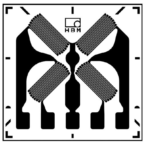
- Installation of strain gauges
- Utilization of screw-on type strain transducers, sometimes even with integrated electronics
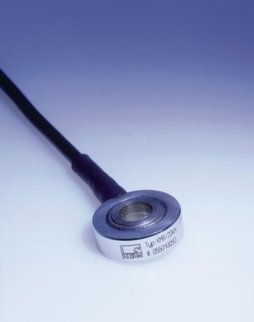
- Utilization of force washers, based on strain gauge or piezo technology
The table shows the key advantages and disadvantages of the methods presented: