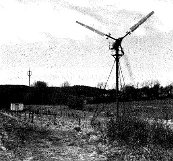
The ET 4063 research project, funded by the German Federal Ministry of Research and Technology and the Industry [1], has clearly shown that the wind energy can make a contribution to securing our energy supplies. Fig. 1 shows the entire pilot plant used at that time.
Torque measurement in wind turbines - as relevant today as it was in the past
Torque transducers used in the 1980s
In the course of the research project, the T30FN torque transducer offering 10 kN•m nominal (rated) torque was used.
The F in the type name refers to the frequency-modulated signal transmission method. This means contactless measurement signal and energy supply of the rotor without any influence of the coupling factors, for example air gap variations.
The N in the type name designates integrated magnetic rotational speed measurement. The mechanical power as the generator input quantity can be determined from torque and rotational speed.
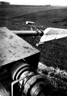
Fig. 2 shows the torque transducer installed on top of the mast.
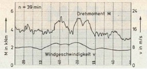
Fig. 3 clearly shows the relationship between wind speed and torque [2]. Torque increases with increasing wind force - while rotational speed remains unchanged. The result: Additional mechanical power is generated. However, this also means that the generator can produce more electrical power.
Status quo: Wind energy today
Today, the wind energy is one of the major renewable energies and continues to be a market of the future with attractive growth rates. Furthermore, energy requirements have rapidly increased and the demand for alternative forms of energy has virtually exploded as a result of nuclear phase-out.
At the beginning of the 1990s, a wind turbine's average rated output was 200 kW. Today, it amounts to 2 MW. There has been an increase in rated output by factor 10 over just under 15 years. This increase mainly results from larger rotor diameters. Doubling the rotor diameter gives a quadrupling of the effective area.
Mechanical measurement quantities of a wind turbine
The output of a rotating body is obtained from the product of torque and angular speed.
![]()
P = Output in N•m/s (1N•m/s = 1 W = 0.00136 metric hp)
M = Torque in N m
ω = Angular speed in s-1
N = Rotational speed in rpm
![]()
Transformation and some other steps give the relationship for torque, the quantity to be measured.

The calculated torque must by no means be directly used as the basis for selecting the torque flange, because it does not take into account any additional influencing factors, for example starting performance or vibration. General information about torque measurement is provided in [3].
Gear unit
In wind turbines, there is a "conflict of interests" between the rotor's drive speed, limited, for example, by pitch speed, and the required rotational speed of the generator. With two pole pairs, a rotational speed of 1500 rpm is required for a mains frequency of 50 Hz. [4].
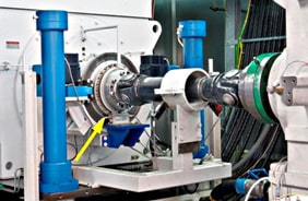
The solution is to use a gear unit. Gear units convert rotational speed and torque and transmit high power. In a modern multi-megawatt wind turbine [5], they are used to convertthe rotor's low rotational speed of approximately 14 rpm into the generator shaft's high rotational speed of approximately 1400-1650 rpm. This conversion involves a reduction of the high rotor torque according to the gear ratio. Fig. 4 shows a type T10FM* torque flange from HBM with 40 kN•m nominal (rated) torque used at the generator input end.
Wind turbine gear units weigh many tons and in most cases are compact, combined planetary-spur gear units. Even though wind turbines without a gear unit are being discussed today, the torque generated by the rotor blades will always need to be very high to generate sufficient electrical power.
* The T10FM torque flange isn't sold by HBM anymore. Follow-up model is the digital T40FM torque flange.
Torque
Torque to be measured often ranges from the kilonewton range (kN•m) up to several Mega-Newtons (MN•m).This is to be illustrated by the following example:
Generator: P=2 MW
Gear unit: 1:100
The generator power of 2 MW and a rotational speed of 1500 rpm give the following formula:
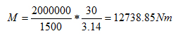
(1) MD=12.74 kN•m / n=1500 rpm
(2) MD=1.3 MN•m / n=15 rpm
Bigger generators with lower rotational speeds are being discussed. However, the torque transducers will then reach their limits as well. Fig. 5 shows the implementation of a 1.5 MN transducer and a design proposal for higher nominal (rated) torques.

Fig. 5: Implementation of a 1.5 MN transducer and design proposal
However, the traceability of a calibration of this huge torque transducer is not guaranteed. The German National Metrology Institute (PTB) in Brunswick, Germany, houses the world's largest torque calibration machine at present. It enables test equipment up to 1.1 MN torque to be calibrated with 0.1% measurement uncertainty [6]. HBM's current torque calibration offer is shown in Fig. 6.
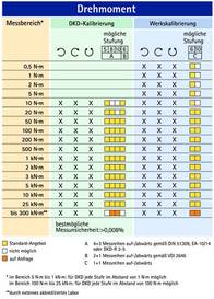
Fig. 6: HBM's torque calibration offer
Conclusions
This article clearly shows how important torque measurement in wind turbines was years ago and still is today. There is no power generation without rotation, hence, there is no power without angular speed and torque.
References
[1] Herbert Lauer: Die Windkraft meßtechnisch erfaßt, Markt&Technik No. 44 dated October 30, 1981
[2] MESSTECHNISCHE BRIEFE, MTB 17 (1981) Issue 2, Published by Hottinger Baldwin Messtechnik GmbH, 64293 Darmstadt
[3] Rainer Schicker, Georg Wegener: Measuring Torque Correctly, ISBN 3-00-008945-4
Published by Hottinger Baldwin Messtechnik GmbH, Darmstadt
[4] energiewelten.de
[5] Christian Scheer, Rainer Schicker: Energie wird knapp. Getriebe und moderne Drehmomentmesstechnik tragen zur Energieerzeugung aus Windenergie bei, Windkraftkonstruktion