Weighing modules Weighing modules | HBM

Utilization of weighing modules for load cells to avoid incorrect loading

For the most part incorrect loading can be avoided utilizing adequate mounting parts. The load cell and the mounting part together form a complex functional unit, a weighing module for load cells. HBM weighing modules come pre-assembled. They can instantly be installed and put into service on site without any additional measures being required.

Depending on their type and mode of operation, weighing modules may include the following components:

  • Upper and lower mounting plate for fastening onto a foundation or other carrier or superstructure
  • Load application and output to the load cell
  • Return to its original position in the event of side forces with pendulum bearings
  • Damping of vibrations or dynamic loading using elastomer bearings
  • Restraints against side force through horizontal stay rods
  • Anti-liftoff device with simultaneous unloading of the module

Note: Not all weighing modules for load cells include all components specified. In part, they cannot be optionally retrofitted!

Selected features of various HBM weighing modules

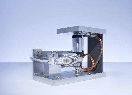
HBM weighing modules can be fitted with OIML R60-compliant load cells and are thus also suitable for legal-for-trade applications.

Benefits of HBM weighing modules:

  • Maintenance free
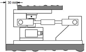
  • Space-saving installation through minimal height of construction
  • Easy mounting
  • Galvanized or stainless-steel versions available
  • EEx(i) load cell version available on request
  • Partly fitted with anti-liftoff device
  • Fitted with stay rod
  • Selected modules available with overload stop

Note: Not all weighing modules for load cells include all components specified. In part, they cannot be optionally retrofitted!

HBM aims to continuously expand the range of weighing modules. Please refer to the latest product catalog for information on new components.

Configuration of weighing modules according to the application

The stay rods absorb side forces up to the maximum value specified in the weighing module's operating manual. To avoid damage, this maximum value must in no case be exceeded. If this cannot be guaranteed, additional protective measures need to be taken. Furthermore, it is essential to note that the stay rods cannot absorb any lateral forces.

The most favorable configuration needs to be identified already before installing the modules on site. It is essential to take into account individual circumstances, for example, wind loads, the tank volume, side forces, dilatation and thermal influences already during the design. On the one hand, the direction of the stay rods needs, without exception, to conduct all occurring loads through the stay rods while maintaining permissible limit values, on the other hand, temperature dilatation which may exert significant force must not be impeded. The mounting directions suggested by HBM can only provide approximate figures. The configuration of the weighing modules needs to be checked and matched to comply with static, dynamic and thermal loads for each project individually.

Note: When a tank is supported by four points (four modules), one support should be designed without any restraint by a stay rod (Fig. 5) to avoid restricting compensating movements and to avoid damage to the modules.

Fixed bearing as a cost-effective module substitute

Fixed bearings can be used as both mounting accessory or module substitute. Using only one or two "measuring modules", depending on the form of the tank, enables substantial material and installation cost savings to be achieved. To ensure sufficiently precise measurement results, this is only possible with tanks whose center of gravity in the vertical direction is not affected by the filling process. In most cases, this is, however, only true for liquids and, possibly, pourable bulk material. These cases too require that the optimal alignment of fixed bearing and modules is identified. The fixed bearing features maximum stiffness in the longitudinal direction of the web and maximum flexibility perpendicular to the web. Wind forces and their influences on the weighing result need to be taken into account here.

Effects of mounting

Unevenness of the contact surface

A surface unevenness of less than 0.6 mm is required. Greater unevenness needs to be leveled with sealant, for example AFM-30 (from Reinz).

Angle of inclination of the contact surface

The load cell's sensitivity is reduced by 1-cosα. This deviation is compensated for via the weighing electronics during calibration of the weighing system. However, an angle of inclination of 3° must not be exceeded.

Plane parallelism

If base and top plate are not parallel to each other, this deviation of the force application parts from plane parallelism results in additional lateral force. This lateral force is absorbed in the longitudinal direction by the stay rod. In the transverse direction the pendulum support is deflected to such an extent that the equilibrium of forces is restored. However, to reduce the effect of lateral forces to a minimum, the angle of inclination must not under any circumstances exceed 3°.

Axial offset

An axial offset between cover plate and force application to the structure is acceptable since the plates are screwed together.

Download the article as pdf