Load application in load cells Load application in load cells | HBM

Load application in load cells - Tips for users

Correct load application on the load cells is a prerequisite for precise weighing results. Be it load direction, support structure or mounting aids – load application is influenced by multiple factors.

Special attention must be paid to the load application points on load cells as well as the contact points between the load cell and the load being weighed, and between the load cell and its contact surface.

Load components that do not act in the assigned measurement direction of the load cell distort the measurement result and may shorten the operating life of the load cell.

Load cells should only be used in the specified load direction. The load direction is identified on many HBK load cells by an arrow. With some load cells (e.g. Z6, Z7A and HLC), +/- loading is also possible in non-legal-for-trade scale arrangements when this load axis is observed.

Side forces and bending or torsional moments should be avoided whenever possible. The figure shows correct loading of a load cell (a) as well as some selected examples of incorrect loading in diagram format.


Image descriptions:

a) Central load application 

b) Non-central load application

c) Non-axial load application or side forces

d) Moment-loading (torsion) load application

Support structure of load cell arrangements

Load cells for compressive loading must rest with their base on level load-bearing support structures. The surface must not be deformed by the load. To ensure even transfer of load from the base of the load cell to the support structure, the load cell must be fastened onto a rigid base plate. This is urgently required, for example, if the load cells are resting on sectional beams that are supported mainly by the belts. The support structure of the load cells must be able to apply the support forces corresponding to the load.

Although the support structure may be severely deformed by the effect of the load in some circumstances, standing safety is completely guaranteed.

These deformations may also cause the supports to lower at the same time. If the supports actually do lower, it should be by the same amount for all supports so that tilting, which results in changes in the proportional load distribution and lateral forces, is avoided.

Normally a rigid design is better suited for the support structure than a pliable one. A pliable design makes it very difficult to achieve even lowering of all supports. Tension may also be present throughout the entire structure.

Mounting aids for load cells

When weighing tanks or monitoring levels, thermal expansion and the horizontal movements associated with it must be taken into consideration for both the tank and the support structure. A rigid installation prevents these movements and ultimately induces horizontal forces that are frequently sufficient to distort the measurement result. The load cells are occasionally damaged or even destroyed by these effects. Similar consequences may result from introducing loads that are overlaid by torsional moments and side force components. Examples of this are eccentric loading or forces that are introduced at an angle. Accordingly the installation shapes must be chosen to ensure that horizontal forces resulting from thermal expansion or other sources are taken into consideration or better still excluded.

The elements used for this purpose and described here each provide a specific solution to the problem depending on the shape of the tank. Mounting aids help ensure compliance with the installation guidelines for load cells. Points of emphasis for eliminating disturbance variables are extraordinarily diverse with each one requiring an application-specific approach. Ultimately the design engineer with detailed knowledge of the product determines the weighting of individual disturbance variables. Not only is there a wide range of options for introducing loads with different models of load cells, there are also many different types of mounting aids available.

Elastomer bearings

Elastomer bearings typically include a number of steel plates and layers of rubber arranged on top of each other and connected to each other by vulcanization. A small amount of force can be applied to move both the upper and lower load application surfaces towards each other while remaining parallel. This makes it possible for the top bearing plate to yield when a side force is introduced without transferring any additional weight force effect to the lower plate of the load cell. In this manner a horizontal deflection of up to 15 mm can be achieved between the tank and the load cells. This deflection is permitted by the elastomer bearing, but maximum deflection results in a noticeable decrease in weighing accuracy.

When deflection occurs, restoring forces develop simultaneously to bring the tank back to its original position. This force acts proportionally to the deflection and independently of the load. Depending on the type of elastomer bearing, a force of up to 800 N may be applied. The bearing compensates for tanks positioned at an inclination of up to 1.7°.

Especially in the case of shock loads, vibrations and other externally induced vibrations, the damping effect of the elastomer bearing has proven to be advantageous. Elastomer bearings also insulate heat as a result of their design, with the structure of layers minimizing the unwanted transfer of heat between the tank and the load cell.

Lateral deflection can be limited simply by providing end stops. There is no need to use linkage elements.

Caution
When the tank being weighed is connected, the elastomer bearing is shortened by about 1 mm when the maximum capacity is applied. This is considerably more than the actual displacement of the load cell itself and could lead to grave measurement errors.

Although conventional stay rod restraints are not used, precautions should be taken to fix the tank in place, especially if the center of gravity is in an unfavorable location. Elastomer bearings are inexpensive components for use in weighing tanks. They are easy to use in terms of their design and suitable for low to moderate accuracy requirements.

Pendulum load cell

Self-centering pendulum load cell

These load cells automatically guide the superstructure back to its original position when the load is introduced with lateral displacement (inclination). The process makes use of a well known principle of physics, the state of stable equilibrium. The load cell, acting as the body of a pendulum, has load application surfaces with a total of bending radii greater than the height of the load cell. A deflection thus causes the load to be raised, which in turn causes it to return to its original position.

The maximum permissible deflection specified in the data (for example a maximum of 13 mm / 5° for type C16/40t) must never be exceeded. Doing so could damage the load cells or load application points. The problem can easily be solved with suitable adjustable stops on the superstructure. In many cases, however, it will also be necessary to use stay rods in this installation situation.
Two HBK thrust pieces, one on the top and one on the bottom, are inexpensive and easy to install and adequate for this purpose. A rotation stop prevents impermissible rotational movements around an object's own axis.

The self-centering HBK C16A load cell is currently available as a pendulum load cell with maximum capacities from 20 t to 400 t. They are suitable for moderate to high accuracy requirements.

Pendulum bearing and pendulum support

A pendulum bearing and pendulum supports make it possible for standard load cells with beam profile and C-type profile to achieve properties similar to those of self-centering load cells. In this manner the tank weigher setup can meet high accuracy requirements. The design of the pendulum bearing mounting parts allow for a deflection of about 3° without any significant measurement errors. Horizontal displacement of support points is therefore possible within limits. While ZPL pendulum bearings usually consist of two thrust pieces and one cylinder piece, only one cylinder piece and one EPO3 thrust piece perform the relevant function in the ZPS pendulum support.

When the pendulum bearing is deflected, the load is raised slightly compared to its original position. This produces a restoring force which returns the system to its original position. Pendulum bearings and pendulum supports can thus be considered as self-centering. They are easy to handle when used as mounting aids during installation. Lateral stay rods are not required to restrain a platform in place. Limiting lateral deflection with end stops is recommended, however. Stay rod restraints must always be provided for tanks with stirrers. As noted previously regarding the use of elastomer bearings, for safety reasons the tank must also be protected against being raised or tipped ove

Loading foot

A loading foot is especially useful for HBK series HLC load cells when used together with a platform scale setup. The load is introduced via a rocker pin. The mobility of the pin permits movements to compensate for the different loading states and temperature changes of the scale. The load can be introduced at an adjustable height, which makes it easy and effective to adjust the height of the platform while it is being mounted. No other restraining or mounting elements are needed. Load feet allow for a very flat, simple design of this type of platform scale. Because of the properties described above, systems of this type are frequently used when the installation location of the scale is subject to change.

Additional design components

Cone and conical pan

Traditional scale manufacturing was able to achieve extremely high precision with mechanical scales. The mounting aids "cutter and blade" for hybrid scales as well as "cone" and "conical pan" can be used for individual load cells to draw on this proven function.

These mounting aids are provided especially for weighing technology applications with heightened accuracy requirements and in the legal-for-trade range. Dynamic loading or vibrations are incompatible with this application in all cases.

Fold-back arms

Fold-back arms are used together with load cells in the double bending beam format. They allow for moment-free loading with tensile or compressive forces on their pitch line. Possible uses are generally limited to applications with only one load cell within a platform or together with knuckle eyes placed on both sides for a suspended load.

Knuckle eyes

Knuckle eyes are suitable for use with a quasi-static tensile load (load cycle = 10 Hz). The remainder of the connection is generally made with fork pieces. Pliable tension bars should be used for dynamic loads with higher frequencies.
The table in Figure 4-10 is provided to simplify the user's selection of the corresponding mounting aids and accessory components available for the relevant load cell. The latest HBK product information about other new components is recommended for additional information.

Fixed and rocker bearings

If not all the tank brackets are placed on the load cells, either fixed or rocker bearings are used instead. If a fixed bearing is used, ready-made components can be used to some extent. The illustration shows the fixed bearing delivered by HBK, consisting of a double T carrier fitted with struts. The struts produce a defined bending zone. The fixed bearing restrains the tank in the horizontal direction as well, which makes it possible to eliminate linkage elements. Note that the bending zone of the fixed bearing may be raised slightly by the displacement of the load cell, which will result in distortion of the measurement signal. This distortion can be reduced considerably by making adjustments with defined weights, however.

Overview of available mounting aids and accessories:

 C2C2AC16AU2AZ7AZ6RSCHLC
Thrust pieces     
Elastomer bearing   
Pendulum bearing    
Knuckle eye     
Cone, conical pan       
Installation module     
Load foot      
Easy top       
Base plate       


Fixed bearing

The distortion of the measurement signal is practically absent for rocker bearings, because in that case only slight rolling friction is present instead of a bending stress (⇒). However, the horizontal restraint of the rocker bearing is significantly less than with fixed bearings, so that linkage elements may be necessary after all depending on the application. In practice, pliable elastic covers of rocker bearings have proven effective for preventing contamination and possible degradation in the rocker function associated with it.

Fixed and rocker bearings are only recommended if accuracy requirements are not high and if position of the center of gravity in the tank only changes horizontally. This is primarily true for liquids and free-flowing media.


Example of a rocker bearing

Tank restraints

Stops

The design of a tank weigher setup is based on load cells, which either allow for movement by means of appropriate mounting aids or are themselves movable. Depending on their mechanical principle, the mounting aids are to some extent self-centering or self-restoring. This means only a mechanical stop would be necessary at the distance of the maximum permissible lateral displacement. Angle stops as well as rubber pads have proven effective in this case.

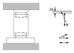
Anti-liftoff devices

If the center of gravity of the tank is above the support points and the effects of wind or other external forces cannot be excluded, the tank must also be protected against tipping or lifting.

This can be achieved by stops on a second level or by a special anti-liftoff device. An anti-liftoff device can be implemented, for example, by vertical threaded rods used in the vicinity of the support points. The threaded rod is guided through a hole in the foot on the tank side with no contact. In that case the maximum distance between the support and tank bracket is determined by a nut found on the threaded rod. The size of the hole in the tank bracket also makes it possible to restrict the maximum lateral displacement.
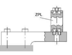
 

Stay rods

When non-self-restoring bearings are used, stay rods are recommended for restraining the tank. The stay rods must be dimensioned and aligned so that they receive externally applied forces, but apply only the slightest possible force in opposition to the movement of the tank.

The following formats have proven effective for stay rods:

Tensioning ropes:
Tensioning ropes do not transfer any forces in the vertical direction, which makes them excellent for preventing unwanted force shunts.


Stay rods:
Stay rods are subjected to a tensile load in the longitudina direction by horizontal forces.

Two stay rods must therefore be used in each axis to ensure complete restraint.
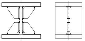
 

Flat stay rods:
In flat stay rods the horizontal displacement that is received results in a longitudinal force. Vertical deflection causes bending that leads to a force shunt. Because the flat stay rod is bent in its direction of pliable bending, however, the effects are relatively minor even if large cross sections are twisted with clamping on both sides. It is essential to take into account the force shunts that occur when making the adjustment.

Clamping the stay rod with symmetrical clamping and screw connections (top and bottom) is especially recommended for dynamic excitation of the weighing system so that the bending distances will be identical with repeated loading.
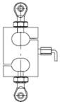
 

Bolt stay rod:
The bolt stay rod results in only very minor force shunts in the vertical direction. However, even a very small tilt in the stay rods may cause clamping effects in the stay rods and therefore friction forces, which lead to vertical force shunts. Mounting therefore requires careful straightening work. The tank restraints must also be set up so the displacements that occur cannot cause the bolt stay rods to tilt.


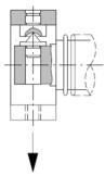
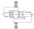
Stay rods with rod end bearings:
Stay rods with rod end bearings behave essentially like bolt stay rods. Because the pivot joint bearing is free to move on all sides, however, tilting is avoided. Other than the horizontal alignment of the stay rods required during installation, these stay rods with rod end bearings are insensitive to manufacturing and installation tolerances of the tank construction.
To avoid the danger of the joints seizing, the rod end bearings must be protected if they are used externally.

In the final installation position the rod end bearings should be offset by 90° (in contrast to what is shown in Figure 4-18) so that they are integrated into the structure offset from each other.