T40B with Rotational Speed Measuring System and Reference T40B with Rotational Speed Measuring System and Reference | HBM

T40B With Rotational Speed Measuring System and Reference Pulse

The market offers countless options for incremental rotational speed measurement systems. However, these systems are designed solely for measuring rotational speed. Combining rotational speed and torque measurement capabilities in a single measurement sensor imposes unique demands on the measurement of rotational speed:

  • The mechanical and application-specific features of the measurement sensor must not be impaired by the speed measuring system.
  • A high-resolution system that simultaneously allows large relative motion between the rotor and the stator is required.
  • The integrated rotational speed measuring system must not interfere with the transmission of the required nominal (rated) or limit torques.

Integrating the rotational speed measurement system with the transducer greatly facilitates handling. If necessary, the second shaft end is no longer required for a speed measuring system and is available for other tasks, such as an additional torque sensor.

Implementation of a Rotational Speed Measuring System

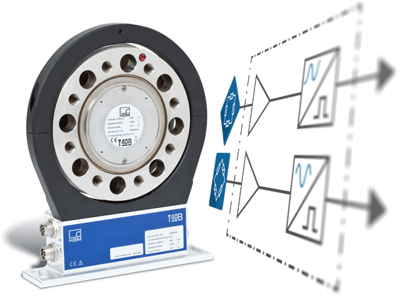
The magnetic plastic ring's metal carrier is mounted onto the torque transducer's second free sensor, so it is fully integrated. This saves space and significantly facilitates installation.

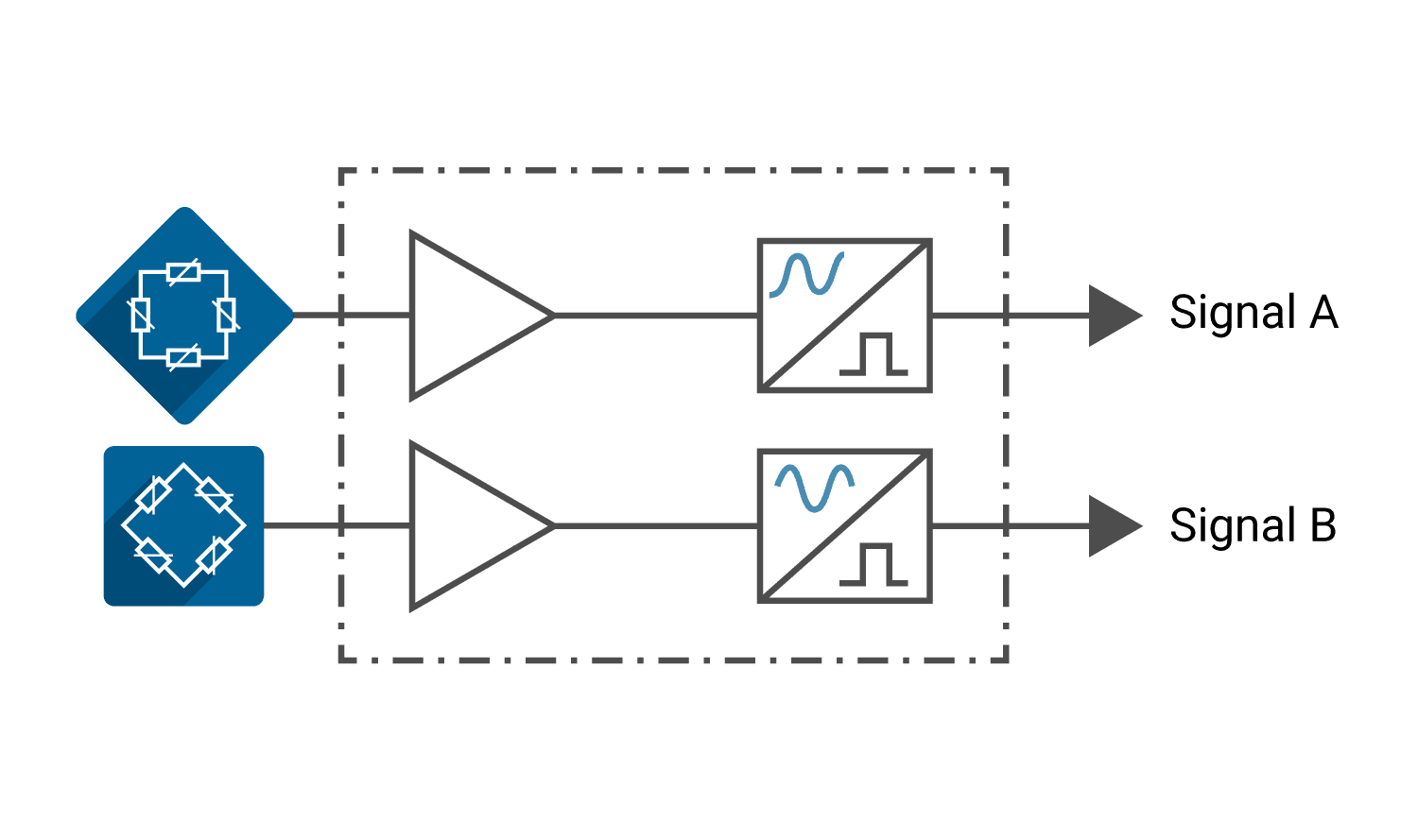
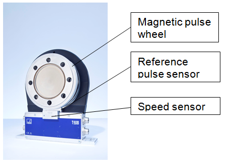
The system is based on contactless sensing of a magnetic pulse wheel using an anisotropic magneto-resistive (AMR) sensor. When the sensor used is subjected to a magnetic field, its resistance value changes, depending on the angle of magnetization and the resistor's direction vector. The magnetic field is modulated by the relative motion between material measure and sensor. The magnetic field is sensed in radial direction. This guarantees a robust and stable signal. The maximum air gap between pulse wheel and sensor is 2.5 mm.

This makes the measurement system extremely insensitive to the relative motion between rotor and stator that can result from vibration in the test bench.

Pulse Generation by a Bi-directional Encoder

The magnetic incremental encoder generates pulses when the drive train is rotated. The number of pulses per revolution corresponds to the speed or position. The system available is a bi-directional encoder; that is, the AMR sensor used includes two full bridges for signal acquisition. The two bridges are arranged offset from each other by a quarter of a period. The generated sine and cosine signals are digitized by downstream electronics. The periodic sine and cosine signals are further subdivided by interpolation, thereby further increasing the basic resolution by electronic means. This reduces the quantization error; calculation of the input shaft's current rotational speed provides results that are more precise.

Output Signals

Two square wave signals that are 90 degrees out of phase electrically are available as output signals. The second signal (signal B) enables decoding the direction of motion (right - left).

With clockwise rotation (that is, to the right), signal B is one phase ahead of signal A. With a rising edge of signal B, signal A is on 'low level.' This corresponds to logic "0". With anti-clockwise rotation (to the left), signal A is one phase ahead of signal B. With a rising edge of signal A, signal B is on 'high level.' This corresponds to logic "1".

The out-of-phase signal pair A and B is also called a quadrature signal, because it allows increasing the resolution further. Signals A and B now generate one pulse per pole pair. The resolution can be increased, for example, with every edge of signal A and B triggering a pulse. This is known as quadruple evaluation. For the T40B and T40FM's rotational speed measuring system, this means that the resolution of 1024 pulses per revolution can be increased to 4096 pulses per revolution.

Incremental transmission from the rotational speed measuring system to the drive controller offers the advantage that only two signals are required for transmitting information about direction of motion, speed and relative position. The disadvantage is that the absolute position is no longer known after a power failure because the rotational speed measuring system measures only the change compared to the initial position. With positioning systems, however, it is essential to know the absolute position. For this reason, a so-called reference run is performed at power-on. This requires a reference pulse (0-index).

Reference Signal

Fig. 4 shows the third signal, which is the reference signal (0-index). This signal is generated by a separate sensor, which senses the corresponding magnetic field in axial direction. It is synchronized with the rising edge of signal A. After power-on, the rotational speed measuring system needs to be rotated until the reference pulse has been detected. The absolute value of the angle is available at the latest after one revolution. This third track generates one pulse per full revolution. Determining the rotor position or the positioning accuracy demands high angular resolution. With quadruple evaluation of the quadrature signal, the system provides an angular accuracy of 212 steps.

The output stages have been implemented as a symmetric 5V (TTL)-RS422 complementary signal. Differential signal transmission offers the advantage that undesired interference fields affect all signals to the same extent and therefore do not change the signal difference. As a result, digital signal transmission is highly immune to interference, so it is the ideal solution for long cable lengths or for use in areas subject to electromagnetic fields.

Torque transducers from HBM

T40B

T40FM

Download Article as PDF

Advantages

  • High accuracy: 1024 pulses/revolution
  • Angular accuracy of up to 212 steps
  • Integrated sensor optimized for magnetic fields
  • High signal quality and signal-to-noise ratio
  • No additional adjustment between pulse wheel and sensor required
  • Air gap of up to 2.5 mm between pulse wheel and sensor
  • Protected against environmental influences