採用Perception軟體對脈寬調製逆變器進行功率測量 採用Perception軟體對脈寬調製逆變器進行功率測量 | HBM

Power Measurements on a Pulse Width Modulated Inverter with Perception Software

Accurate and highly dynamic power measurements are required for assessing and testing electric drives in industrial applications, and for hybrid and electric vehicles. To be able to evaluate these measurement results, the function and working method of the drive components must be considered. 

The development of electric-hybrid vehicles requires three-phase (3-phase) power measurements on electric drives. This article describes the function of the pulse width modulated inverter as well as the calculation of power values with the Perception software.

Introduction

Electric drives offer a wide range of possibilities for operating road vehicles with regenerative energies. The battery-operated vehicle is one simple and transparent variant.

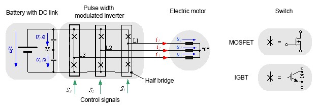
Fig. 1.1 shows the drive train in this type of electric vehicle. The DC voltage of the vehicle battery is converted by the three-phase pulse width modulated inverter into a three-phase current and switched to a three-phase motor. Different power semiconductors are used depending on the amplitude of the battery voltage. MOSFETs (Metal Oxide Semiconductor Field-Effect Transistors) are used for battery voltages below 100 V, while IGBTs (Insulated Gate Bipolar Transistors) are used for higher voltages.  Pulse width modulated inverters can be used to power both asynchronous (Induction) and synchronous machines. Innovative measuring instruments are needed to be able to test and optimize the drive train of an electric vehicle. They must enable both highly accurate power measurements and calculation of various intermediate values.

Pulse Width Modulated Inverter

A pulse width modulated inverter converts a DC voltage into an AC voltage with variable frequency and amplitude. Due to its simplicity, the  two- level inverter is frequently used. Fig. 1.1 shows the circuit diagram of a three--leg, two-point inverter. Each leg of the pulse width modulated inverter consists of a half-bridge with two IGBTs and the corresponding power diodes. MOSFETs can also be used for lower battery voltages. No additional diodes are required for pulse width modulated inverters with MOSFET, as they are reverse-conducting.

A half bridge connects a connection point in the machine (depending on the switching state of the transistors) with the positive or negative pole of the DC link. In the ideal inverter initially considered here, the switches and diodes should not have any conducting losses in the activated state (u = 0), and in the deactivated state, should ideally be disabled (i = 0). The switching state should also involve no time delay.

The working method of a two-point inverter is especially clear when the time curve of the output voltage of a half bridge is considered against a "virtual" medium voltage tap M in the DC link. The inverter voltages eνM with ν = 1, 2, 3, according to the corresponding control signal, can take on the value +Ud /2 with Sν = 1 or the voltage value -Ud /2with Sν = 0.


(2.01)


To calculate the line voltages in the machine, first the mesh equations are set up:


(2.02)


If the correlation u1 + u2 + u3 = 0 is taken into consideration, the zero system of the inverter voltages can be calculated:  

(2.03)


A three-phase inverter has three legs and two switches per leg, resulting in only 2³ =8 different voltage states. This limited number of voltage states has created the need for advanced control in inverters in order to supply variable frequency and voltage amplitude to motors.  Pulse width modulation is a switching control strategy that allows for a spectrum of voltage amplitudes and frequencies to be achieved with the 8 switching states. It does this by supplying DC pulses of different lengths to the motor, which are effectively a sine wave when switched at a high enough frequency.

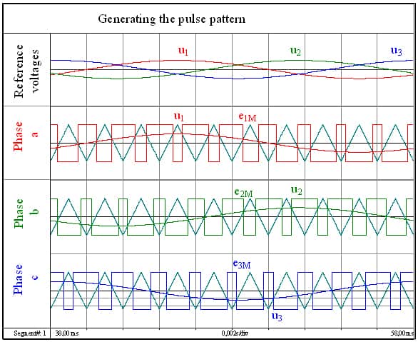
Fig 2.1 shows how the control signals are generated with simple sine-triangle modulation. A triangular-shaped voltage is compared with the desired sine voltage. If the sine voltage is greater than the delta voltage, a positive voltage is generated. The pulse width modulated inverter switches to a negative voltage if the sinusoidal voltage is less than the delta voltage. The frequency of the triangular voltage is equivalent to the switching frequency at which the power semiconductors switch.

 

Power Measurements on the Pulse Width Modulated Inverter

The electrical power cannot be measured directly. Instead it is calculated from the measured current and voltage values. This procedure was previously described. As the star point is usually not accessible, the star voltages cannot be measured directly. The measuring methods are explained below with an artificial star point and with the aid of phase-to-phase voltage.

Measurements with Artificial Star Point

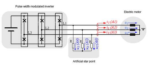
If the star point in the electric motor is not accessible, the star voltages (u1, u2, u3) cannot be measured directly. However, the voltage can be made measurable by an "artificial star point." As Fig. 3.1 shows, an artificial star point consists of three identical high-impedance resistors. The instantaneous power delivered by the pulse width modulated inverter can be calculated with these star voltages and currents (i1, i2, i3).


(3.01)


Fig. 3.2: Diagram showing a power measurement with an artificial star point


Fig. 3.3 shows the result of a measurement with an artificial star point. In this case, the pulse width modulated inverter supplies an asynchronous machine. The currents and voltages are measured in all three lines. Despite the pulsed voltage of the pulse width modulated inverter, the current is still approximately sinusoidal. Therefore, the current signal is used to derive the cycle time for mean-value calculation in the power measurement. It is easy to see whether the cycle time has been correctly detected by comparing the duration of the period of the current signal and the cycle i1 curve.

The phase shift of 120° among the three line-to-line currents can be seen in the diagram. As is usually the case with asynchronous machines, the current lags compared to the voltage.

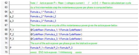
The total effective power delivered by the pulse width modulated inverter is determined by calculating the mean value of the instantaneous power. Equation 3.02 shows the procedure in Perception.

(3.02)

The apparent power S is the product of the current RMS value and the voltage RMS value. The RMS values are calculated over one period. The duration of the period can be determined from the current curve i1 with the cycleDetect command.

The apparent power can be calculated in Perception with the following equations:


(3.03)

The reactive power Q is calculated for each line from where  


(3.04)


The total reactive power is the sum of all individual reactive powers. The reactive power can be calculated in Perception with the following equation:


(3.05)


Power Measurements with Phase-to-Phase Voltages

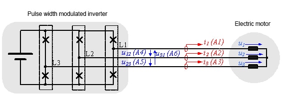
Phase-to-phase voltages can be used to calculate star voltages:


(3.06)


The counting direction of the phase-to-phase voltage can be seen in circuit diagram 3.4. Further calculations are then performed for various power values with star voltages as shown in the previous section. 

The measurement of the voltage at a star point allows for the detection of imbalances in the machine. An imbalance means that one or more phase voltages or currents are not uniform to the others. These imbalances could indicate a problem with the control, motor, or inverter.</p

Summary

This report explained how power measurements are performed on a pulse width modulated inverter. The design and function of a  pulse width modulated inverter were described first. The power measurement was explained with the use of star voltages, with the aid of an artificial star point, and with the aid of phase-to-phase voltages. The power measurement should preferably be performed using an artificial star point, as that makes it easy to interpret the results. All necessary calculations were implemented in the Perception software. Perception users can download the data sets and formulas that are used from the HBM homepage.

Read the whole article

References

[1]    D. Eberlein; K. Lang; J. Teigelkötter; K. Kowalski: Elektromobilität auf der Überholspur: Effizienzsteigerung für den Antrieb der Zukunft [Electromobility in the fast lane: increased efficiency for the drive of the future]; proceedings of the 3rd conference of Innovation Messtechnik [Innovation in Measurement Technology]; May 14, 2013

[2]    J. Teigelkötter: Energieeffiziente elektrische Antriebe [Energy-efficient electric drives], 1st edition, Springer Vieweg Verlag, 2013 

[3]    Berechnung von Leistungsgrößen mit Perception-Software [Calculating power values with Perception software] https://www.hbm.com/de/3783/berechnung-von-leistungsgroessen-mit-perception-software/

[4]    www.hbm.com