Dyno Dynamics: High-Speed Engine Dynamometers Dyno Dynamics: High-Speed Engine Dynamometers | HBM

New Generation of High-Speed Engine Dynamometers

Dyno Dynamics is an Australian company that has been at the forefront of dynamometer design for more than 25 years. They have customers worldwide, from as far as Aruba and Abu Dhabi, with a strong presence in both the USA and UK.

The company's best sellers is their line of 2-wd, 4-wd and motorcycle dynamometers for the automotive service industry, but Dyno Dynamics also manufactures truck, bus, and engine dynamometers, for everything from go-karts to locomotive diesel engines.

They recently chose HBM Australia to supply torque sensors for a new high-speed, high-power engine dynamometer design.

New High-Speed Engine Design

When Dyno Dynamics set out to design a new high-speed engine dynamometer, they knew it would be more than just an upgrade to one of their existing models. With requirements of 10,000 rpm and 1,000 Hp (approx. 750 kW), a new approach was needed.

The power rating was not an issue, Dyno Dynamics has built higher-rated engine dynamometers in the past. It was the 10,000 RPM input speed that needed some thought.

Given other design constraints, they chose to use eddy current retarders, as these are compact, robust, and fast-acting. Dyno Dynamics has shipped thousands of retarders over the past 20 years, with very few in-service failures.

However, off-the-shelf retarders for higher power ratings are generally limited to 4,000-5,000 rpm. The clear solution is a gearbox to reduce the shaft speed to something more manageable.

An off-the-shelf industrial gearbox for the power required would be both large and expensive if Dyno Dynamics could source one.  Was there an alternative?

The solution came from the racing world: the dynamometer is designed for high-power racing V8s.


A V8 supercar differential , complete with oil cooler

With a 2.86:1 ratio, the output shaft speed is reduced to a more manageable 3,500 rpm, and the two output (axle) shafts allow compact fitting of a pair of retarders.

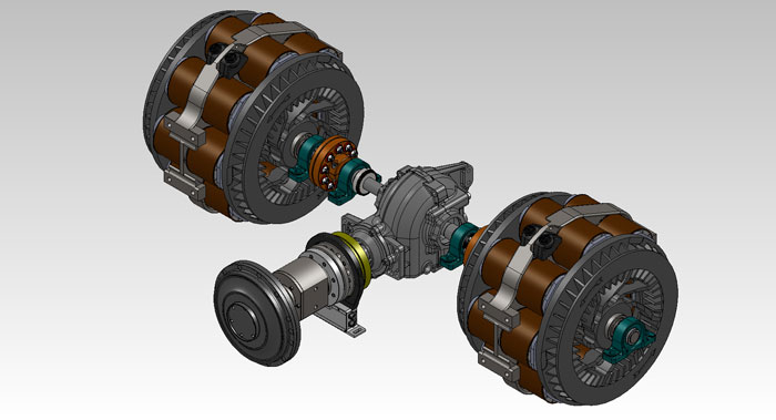
The Solution: A Torque-Damping Coupling

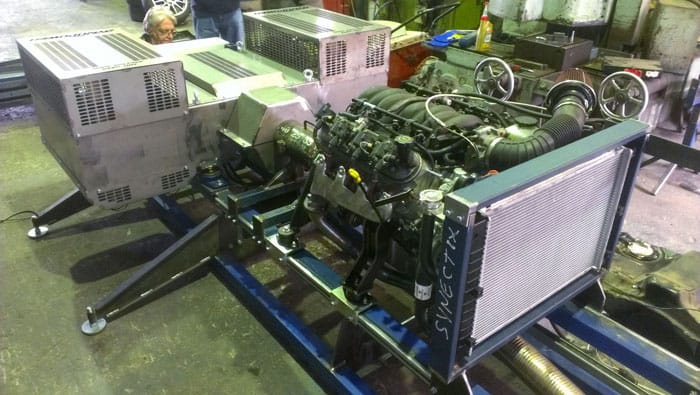
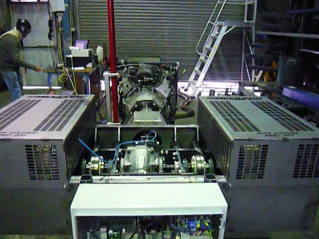
The rotational speed of an internal combustion engine is never constant.  The crank is slowed down by each compression stroke, and accelerated by the power stroke. Although the engine’s flywheel averages out the rotation to some extent, there is still a pronounced speed (and torque) oscillation, especially at low revs.

This oscillation can cause severe stress on driveline components, and this is especially true with engine dynamometers/motors, where there is little “give” in the driveline; no tires or suspension to allow a little flex.

The solution is a torque-damping coupling. This is engineered to a precise torsional stiffness. Peak torques and rotational vibrations of the motor are largely neutralized through the use of the rotational vibration damper, thereby protecting the transmission from excessive wear.

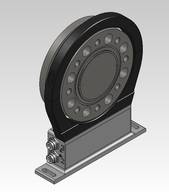
The coupling Dyno Dynamics chose was a TECTOS t600, which is produced specifically for the engine test industry.
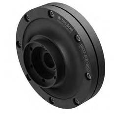
TECTOS t600

With the basic mechanical layout resolved, they focused on instrumentation.

At the heart of a successful dynamometer is accurate measurement of torque and speed. Additional data acquisition is usually required, but torque and speed are critical.

For speed measurement, they used their tried and tested toothed wheel / inductive pickup. These have proven reliable over many years.

Torque measurement was a different challenge. Accurate results require measuring the input torque to the gearbox, so as to include gearbox drag. This meant that Dyno Dynamics could not use the standard torque-reaction arm and load cell.  A shaft torque transducer was required.

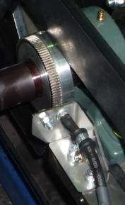
After extensive research, Dyno Dynamics decided on the HBM T40B. With a rating of 15,000 RPM /2,000 Nm, it matched the dynamometer design specs, and its compact profile allowed for a simple mounting layout.

The T40B is a flange-type sensor, with contactless signal transmission. This allows a very compact mounting profile, as the sensor is only 59 mm deep .

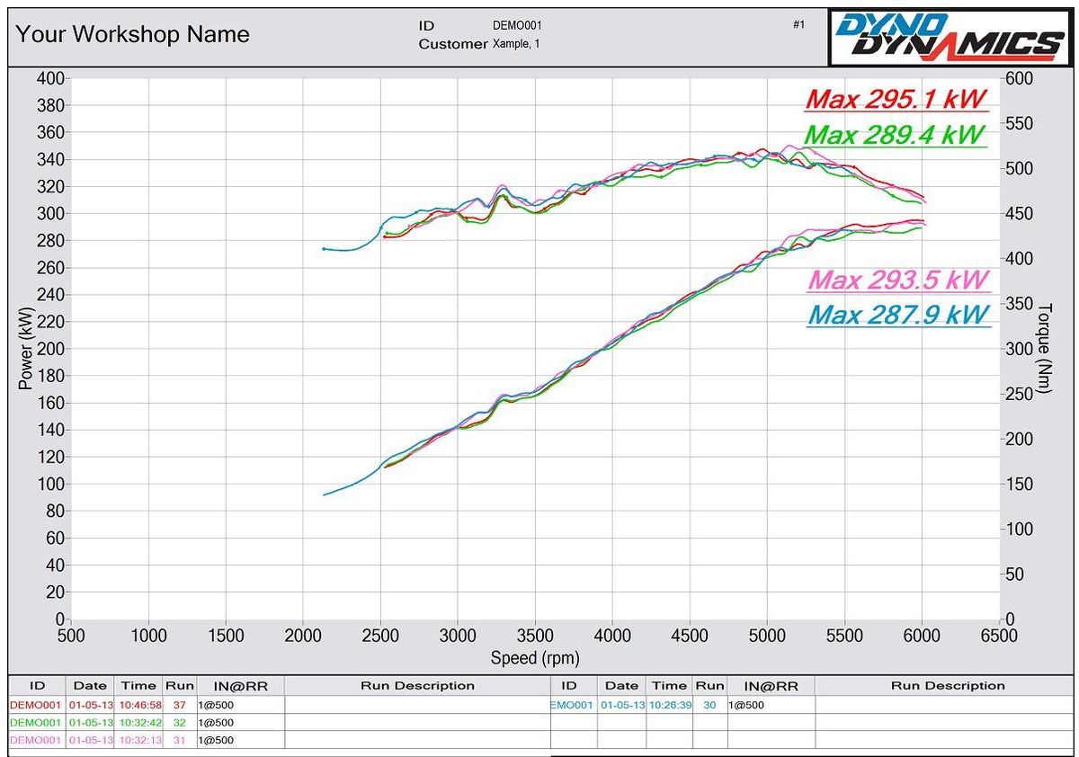
The HBM torque transducer was too responsive and required additional software filtering to smooth out individual cylinder pulses.
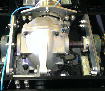

T40B

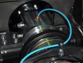
This photograph shows the sensor in-situ: black antenna ring mid-picture

Why Dyno Dynamics Chose HBM

Dyno Dynamics chose HBM as a supplier for a number of reasons. The product fit the requirements at a competitive price, and a major benefit wasaccess to technical support provided by local engineering representatives.

HBM’s sales engineer Michael Lanksch took a keen interest in the project, and came out to the factory to discuss the project with their design team.

The design process was simplified by HBM providing a 3D model of the transducer in SolidWorks format, which integrated with their existing CAD system.

Below is a graph of some early test runs, showing the engine running rough due to inadequate fuel pressure.

Functional principles of dynamometers

All dynamometers need some means of absorbing the power produced by the motor under test, usually converting it to heat. The two most common power absorbers are “water brakes” and “eddy current retarders”.

  • Water brakes effectively use the motor to pump water through a variable restriction, causing the water to heat up. This heat is then removed via a cooling tower of some kind.
  • Eddy Current retarders use the motor to spin a series of disks sandwiched between electromagnets (coils). As the conductive disk moves through the magnetic field, its motion causes inductive heating of the disks. The disks can be either air or water cooled.