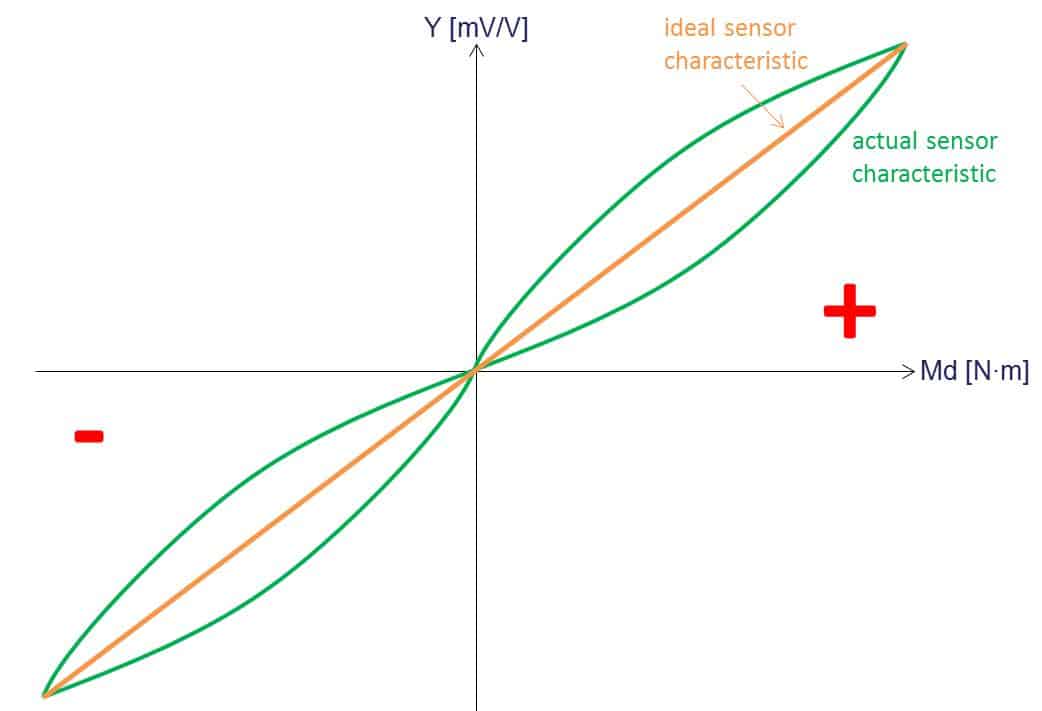
The “classical” method for fast and effective sensor scaling is to use two points. A linear characteristic line is generated that describes the relationship between electrical and physical value. Two-point-scaling is made directly in the sensor channel settings. The data to be entered can be found in the sensor data sheet.
Tips for use: PMX Sensor Scaling Methods
Brief description
These instructions describe various methodsfor scaling sensors in the PMX. In doing so, data from different calibration processes is needed. Scaling in general is understood as the link between an electrical value and a physical value “field value” (e.g. mV/V) -> “process value” (e.g. Newton). For this particular example a DIN 51309 calibrated TB2/200N·m torque sensor is used. Of course those methods can be used with every type of sensor.
The methods of two-point-scaling, value table, polynomial and linear equation introduced here differ mainly in terms of uncertainty and effort. Especially the calculated channel “Polynomial” introduced with firmware 2.02 allows generating two different curves for positive and negative input signals that are used automatically without manual switching. This is very useful with clockwise and counterclockwise torque signals or compressive and tensile load for example.
Important note:
For all scaling methods, with the exception of two-point-scaling, the channel used has to be set to default.
The default settings are:
1. Point electrical: 0.0000000
2. Point electrical: 1.0000000
1. Point physical: 0.0000000
2. Point physical: 1.0000000
Zero value: 0.0000000
Zero target value: 0.0000000
Value table
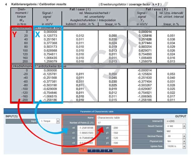
Many calibration protocols include a value table that provides the link between electrical and physical unit by giving a number of various points. Such a value table is shown in the picture below.
Create a calculated channel “Characteristic table” in the PMX and enter the values from the calibration certificate. Start with the lowest values (here: -200). Choose the corresponding measurement channel as input signal.
Polynomial equation
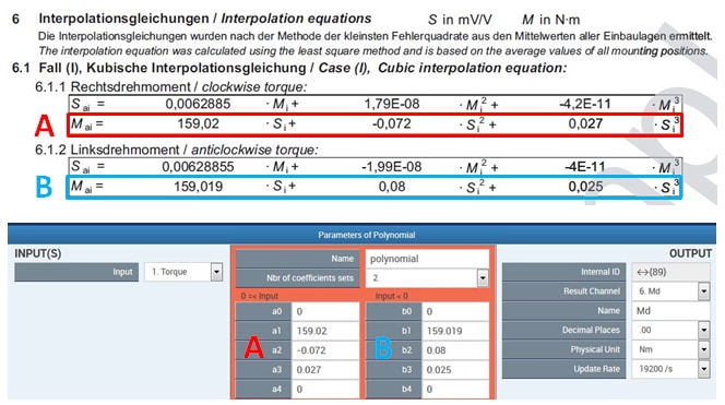
Some calibration protocols also include interpolation equations in addition to value tables.Create a calculated channel “Polynomial” and enter the coefficients of the detuning S. A second polynomial for negative input values can be defined by changing the “Nbr of coefficients sets” in the parameters. This primarily applies for clockwise and counterclockwise torque signals and is usually listed in the calibration protocol. Coefficients A are used for positive, coefficients B for negative input signals. Choose the corresponding measurement channel as input signal.
Summary
The graphic below clearly shows that the cubic interpolation comes closest to the actual value. The uncertainty of the linear interpolation is getting better with an increasing measurement range. The most accurate method however is the value table.
Please note:
The uncertainty of the individual methods is highly dependent on the application and cannot be generalized.
Disclaimer
These examples are for illustrative purposes only. They cannot be used as the basis for any warranty or liability claims.


