FZK: loading by waves in wind power plants FZK: loading by waves in wind power plants | HBM

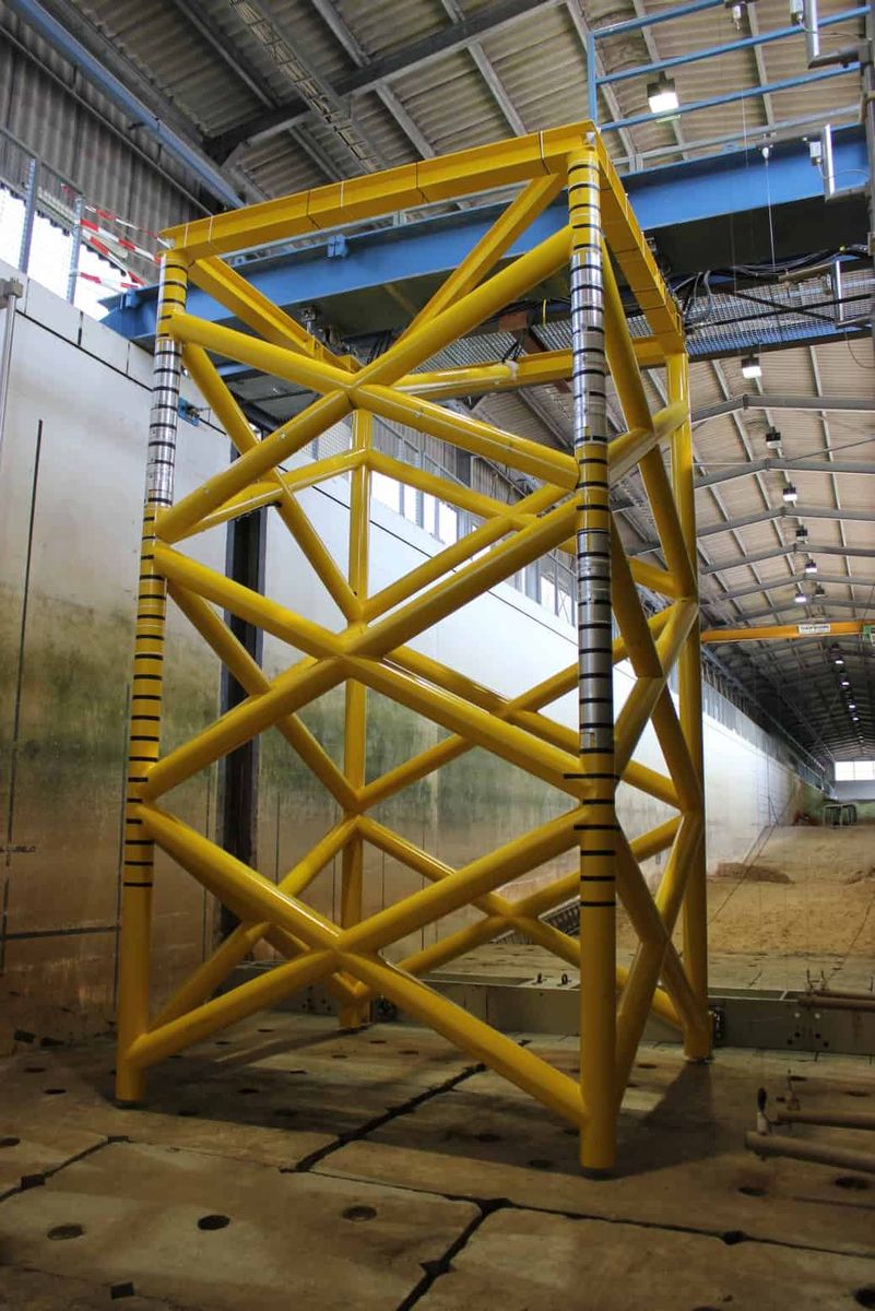
When waves meet wind force

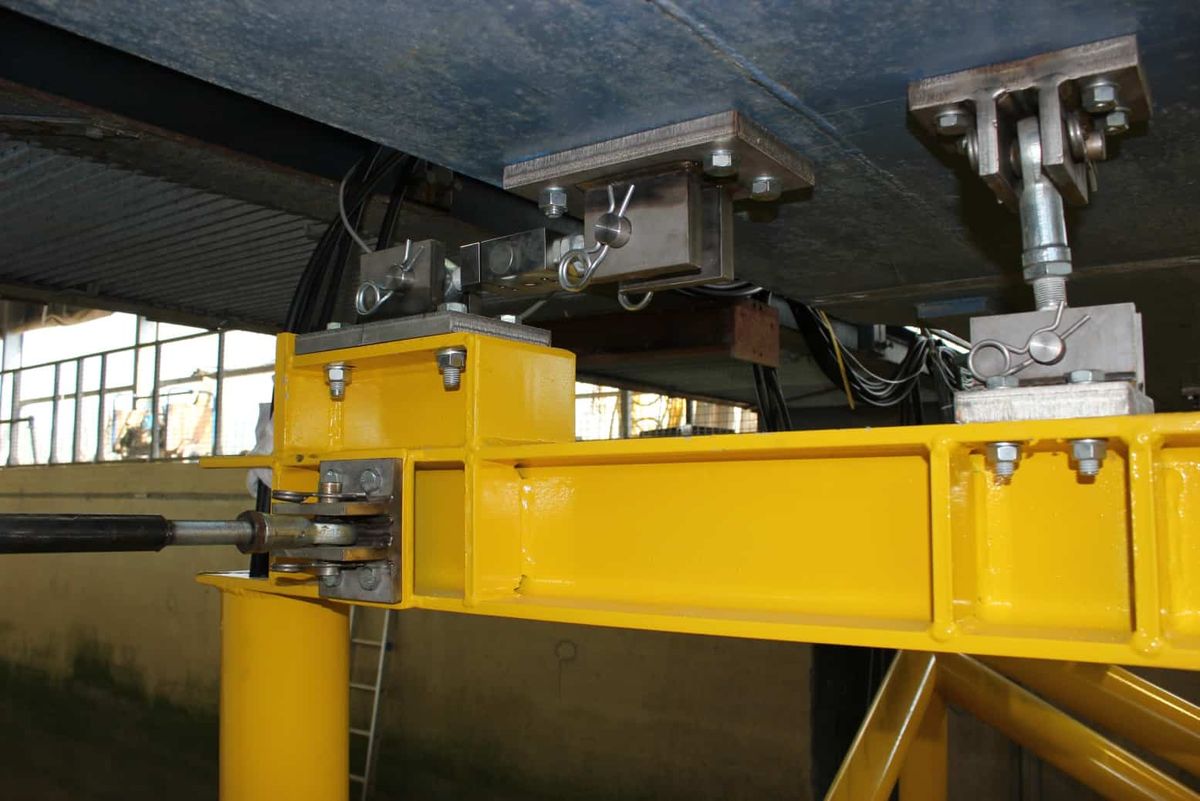
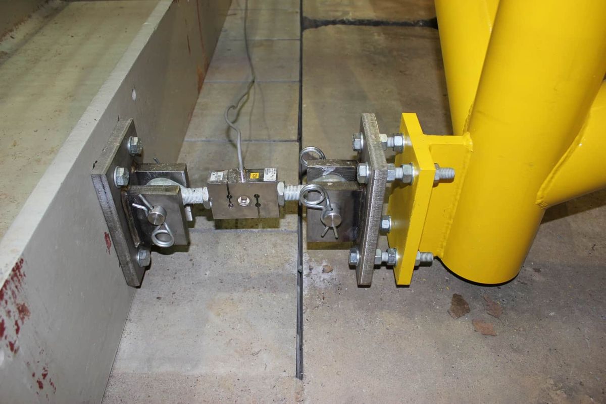
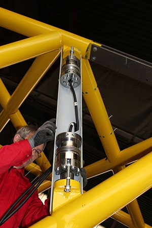
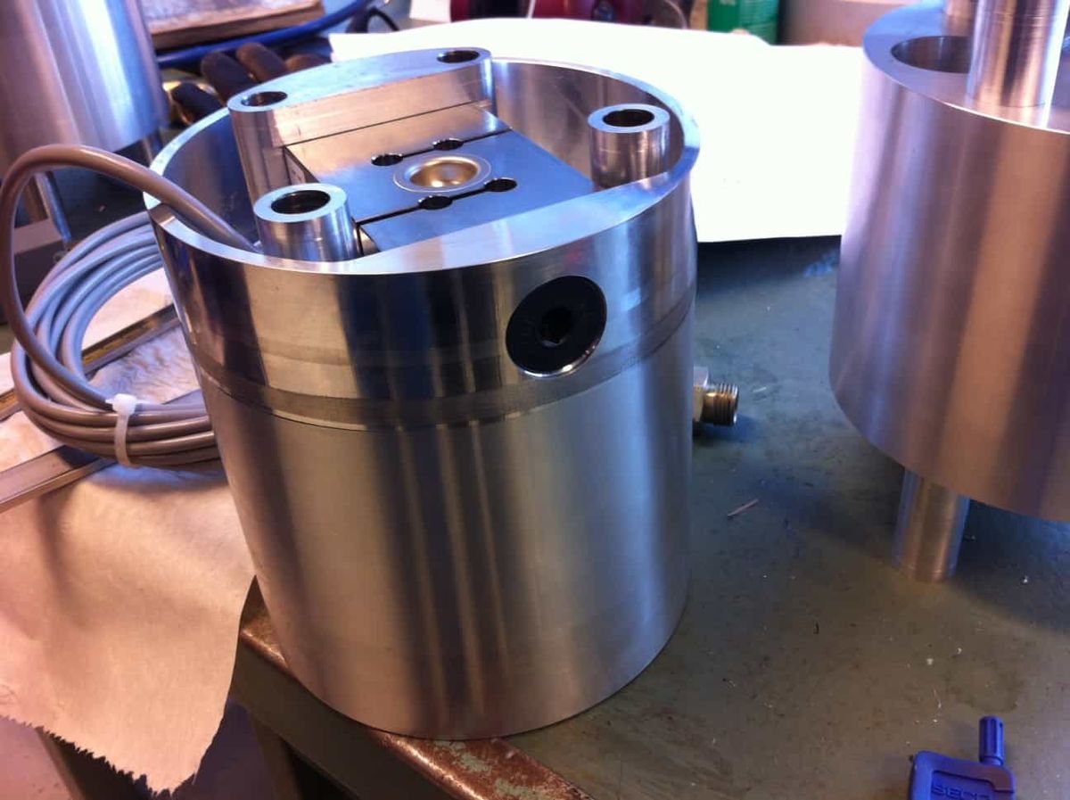
HBM S9M force transducer records the loading exerted by waves on framework structures in offshore wind power plants

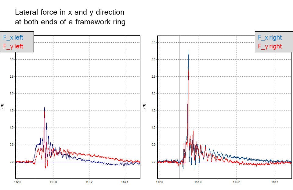
When waves break on offshore wind energy plants, pressure shocks are generated that can load the foundation structures of the plants in shallow water. To improve dimensioning methods in these situations for framework structures, also called jacket structures, physical modelling experiments were carried out at the Large Wave Channel of the Coastal Research Center (FZK) in Hannover, Germany. The S9M force transducer from HBM provided decisive findings.

Loading test in one of the largest wave channels in the world

Especially pressure surges caused by "plunging breakers" are critically important. There are some analytical models that describe loading due to plunging breakers on individual round poles. However, such approaches can only be applied to a limited extent to jacket structures as they are used in offshore wind energy plants. This is not surprising given the different levels of complexity in terms of hydraulic conditions.

To improve dimensioning methods for framework structures subject to pressure surge loading, physical modelling experiments were carried out using a large scale model at the FZK Large Wave Channel as part of the EU research program HYDRALAB IV. The experiments were commissioned by the Norwegian University for Science and Technology (NTNU) in Trondheim and Stavanger University (UiS).

Measuring 320 meters in length, 5 meters wide and 7 meters deep, the Large Wave Channel of the FZK is among the largest in the world. To make optimum use of the 800 kW output of the wave generator, the scaling of the model was defined as 1:8. The waves acting on the structure at this scaling were over two meters high. The rods in the framework consisted of steel pipes 14 cm in diameter. The dimensions of the overall structure were 2.4 x 2.4 x 4.9 m.

All loading recorded metrologically

To record the hydraulic processes and the effects on the selected jacket structure metrologically, the wave channel and the structure itself were fitted with a large number of different transducers:

  • Wave level and flow sensors measured the fluctuation in water level and flow conditions in front of and on the structure.
  • The reaction of the framework structure to wave loading was measured with force transducers and acceleration sensors.
  • A video system synchronized with measurement acquisition provided detailed visual information about the nature of the breaking waves and the wave amplitude on the structure.

The greatest challenge – force measurement

The various force measurements on the structure posed a special challenge. One task was to determine the load distribution on selected framework rods. Another was to determine the total force acting on individual rods and the force acting on the overall structure.

Because the force transducers were intermittently or permanently submerged, HBM force transducers type S9M with degree of protection IP 68 were used to determine the load distribution. Up to four force transducer were placed in individual rods made of solid aluminum. Perpendicular wave loading was measured on 5-cm wide framework rings fastened onto each of these force transducers. The individual measurements were then used to determine the load distribution on a rod.

Four force transducers of the same type were used to determine the resulting total horizontal force acting on the structure. To prevent force shunts, the entire framework structure was fastened onto articulated pendulum supports and the force transducers were fitted on the four pendulum supports in the direction of the wave impact.

HBM developed two-component transducers to measure the resulting forces on six selected framework rods. The six rods were integrated into the jacket structure through two force transducers each. A very compact design had to be developed due to the specified diameter of the framework pipes (14 cm) and the large forces expected (nominal (rated) lateral force of the transducer 20 kN). To prevent loading of the force transducers due to bending moments, they were fastened onto the structure with specially developed ball joints.