Dynamic Power Analysis of 6-Phase Motor | HBM Dynamic Power Analysis of 6-Phase Motor | HBM

Precise and highly dynamic power measurements

The evaluation and testing of electric drives along with the corresponding control strategies in industrial and electrical mobility applications require precise and highly dynamic power measurements. The electrical system in these fields of application normally consists of a two-level inverter, a three-phase electrical machine and the corresponding energy supply.

In this article the topology of the dual two-level inverter (DTLI) is first presented in depth. This is followed by a presentation of the acquisition of mechanical and electrical variables with the GEN3i data acquisition system and calculation of the real-time power values.
The authors

Simon Wolfstädter, M.Eng., Thomas Kowalski, M.Eng., Prof. Dr.-Ing. Johannes Teigelkötter, University of Applied Science Aschaffenburg, Dipl.Ing. Klaus Lang, HBM

Dual Two-Level Inverter

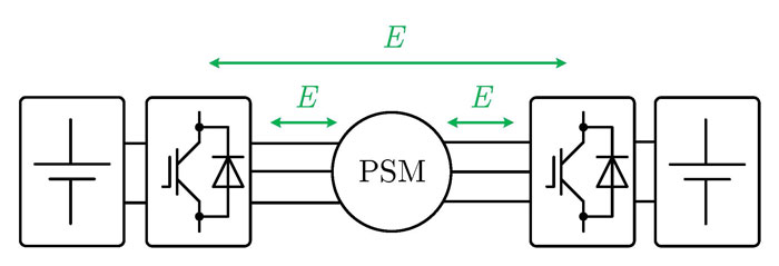
The topology of the dual two-level inverter consists of two individual two-level inverters. The winding strands of the electrical machine are connected between the two inverters. The electrical machine is thus supplied by six phase voltages. Figure 1 shows the topology of the DTLI with separate DC links. The two inverters are supplied by two DC voltage sources, which are also separate.

Some typical advantages of this DTLI topology include improved failsafe performance, reduced DC link voltage (with the same power requirement for the machine) and also the higher number of voltage levels compared to the single two-level inverter application [1].

At the same time the topology makes it possible to distribute the electrical power absorbed or given off by the machine to the two inverters or the energy supplies connected to them. Figure 2 shows the possible directions of energy flow within the system. Those directions lie not only between the inverters and the electrical machines, but also between the two inverters themselves. That means it is also possible to exchange energy between the two energy supplies via the machine winding.

Test bench and measurement acquisition

Metrological acquisition and analysis of electrical and mechanical quantities present in the system requires a large number of measuring points.

In addition to mechanical quantities such as rotational speed, torque and angle of rotation, electrical measured values of the relevant phase voltages/currents, DC link voltage and currents are required to evaluate dynamic and stationary operating behavior.

Figure 3 shows in diagram format measurement acquisition of system quantities which are sent to the GEN3i data recorder.

The test bench and measurement acquisition are structured as follows:

  • The machine being tested is a permanent magnet synchronous machine (PSM), supplied by the DTLI. Each inverter is supplied by a lithium battery bank. The rotor position is calculated by means of a resolver.
  • The operating parameters are assigned by a CAN interface.
  • The dynamometer is a speed-controlled, permanent magnet synchronous machine supplied by a separate inverter. The inverter is operated by a supply device located directly on the supply network. The rotational speed is measured by an incremental encoder.
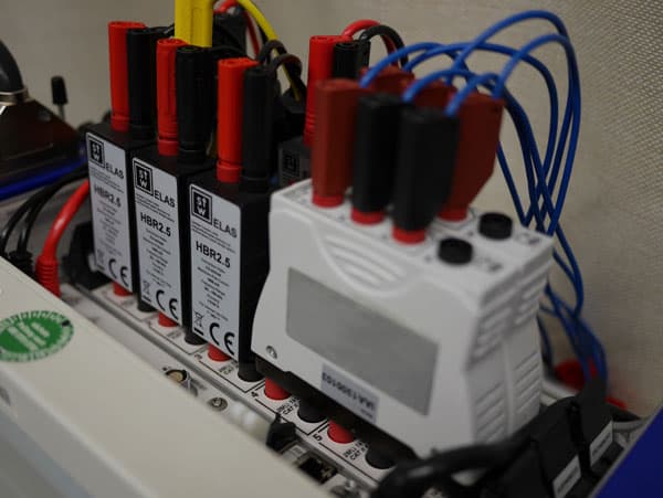
  • The phase currents are measured with high-precision current transformers type LEM IT 400 S. The measuring shunts are the high-precision HBR 2.5 positioned directly at the relevant channel input of the GEN3i.
  • The phase voltages of the two inverters are measured against an artificial star, also directly on the GEN3i.
  • The battery voltages are acquired directly by the high-voltage channels of the GEN3i.
  • The mechanical quantities for torque and rotor position are made available by an HBM T12 torque transducer. It is connected with the GEN3i via the event IO to Txx adapter.

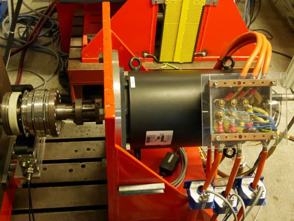
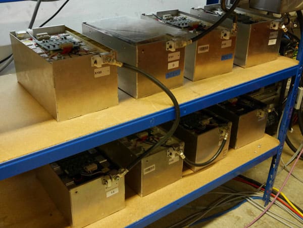
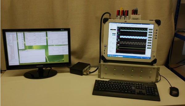
Figure 4 shows the machine being tested with the two-sided connection of the windings. Also visible are the torque transducer, current transformer and the measurement tap for the phase voltages. Figure 5 shows one of the two lithium battery banks for supplying the inverters. Figure 7 shows the input channels of the GEN3i with the measuring shunts for the current measurement and the artificial stars.

Real-time power calculation

The measured raw data can be used to determine the individual system powers [2][3]. The phase quantities are used to calculate the instantaneous powers of the inverters on the output side:

Due to the direction of the counting arrow for the second inverter, negative phase voltages contribute to the positive power output:

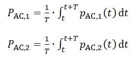
The effective powers are determined by averaging over the fundamental oscillation period T of the phase current:

The effective power of the two inverters on the input side is determined in a similar manner:

The instantaneous power of the electrical machine can be represented as the difference in voltage between the respective phase voltages times the phase current:

Or also as the sum of the two inverter powers:

The mechanical power on the machine shaft is calculated taking into consideration the torque M and the rotational speed n:

Using the efficiency of the inverter, the quantities on the alternating voltage side can be converted to the DC voltage side:

If the efficiency is known and the battery voltage is constant, the relevant battery current can be determined as follows:

Measurement results

The measurements and methods of calculation described in the previous sections were applied in an examination of the machine being tested with the following characteristics: nominal (rated) phase voltage 270 V, nominal (rated) current: 150 A, nominal (rated) torque: 190 Nm, nominal (rated) rotational speed: 1500 rpm, number of pole pairs: 2.

The two IGBT inverters of the DTLI are synchronized, each at a switching frequency of 8 kHz. The two inverters are supplied by lithium battery banks with a nominal (rated) voltage of 210 V each. Two series of tests for determining the operating behavior of the DTLI and the electrical machine are described below as examples.

(A) Energy distribution to the two two-level inverters

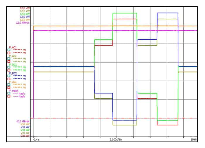
During the measurement the dynamometer is operated with speed control at a constant 750 rpm. The machine being tested is first supplied symmetrically (PAC,1 = PAC,2) by the dual two-level inverter, then asymmetrically (PAC,1 ≠ PAC,2). The torque from the motor is 120 Nm. Figure 8 shows the system powers P calculated by the GEN3i. The input and output powers of the inverters as well as the electrical and mechanical total output are shown. You can see for example that the variation in energy distribution affects only the powers of the first two inverters, not the engine power that is delivered.

(B) Energy exchange between the two-level inverters

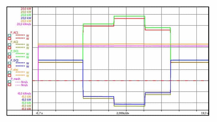
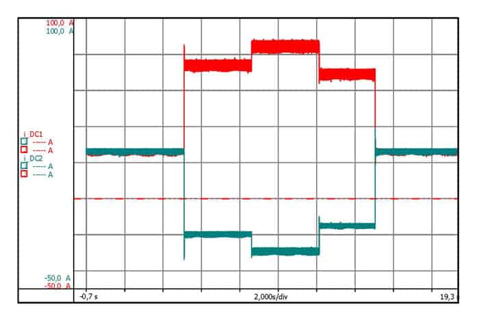
Starting from a symmetrical supply of power with the same machine setpoint as in (A), the energy exchange begins between the two inverters and the lithium batteries. A required load current of 20 A initially and then 30 A and 15 A is assigned for battery 2 (fig. 10). Figure 9 shows the system powers P calculated by the GEN3i. The symmetrical supply of power to the two inverters at the starting point is replaced by the exchange of energy at time t = approx. 4.3 s. Inverter 1 then returns the energy required by the electrical machine as well as the energy required to charge battery 2.

Real-time and post-processing calculation

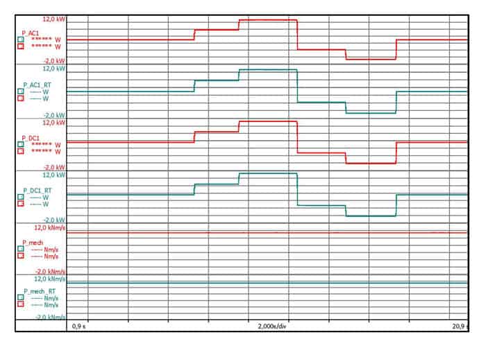
The effective power curves in Figure 11 show the input and output power of inverter 1 as well as the mechanical power and a comparison of the two calculation methods real-time and post-processing for the measurement described in section 4 (A). Both methods return the same results.

Formulas for the post-processing calculation

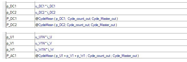
Figure 12 shows an extract from the formula sheet that is used in Perception. The calculations of the two energy storage devices and the output power of inverter 1 are shown here as representative values.

Formulas for the real-time calculation

Implementation of the power calculation in real time is illustrated in Figure 13.

The input and output effective power of inverter 1 are also shown here as representative values. Note there are some differences in syntax between the post-processing and real-time calculation.

References

[1] Grandi, Gabriele; Rossi, Claudio; Lega, Alberto; Casadei, Domenico: Multilevel

Operation of a Dual Two-Level Inverter with Power Balancing Capability. In: Conference Record of the 2006 IEEE Industry Applications Conference Forty-First IAS Annual Meeting, 2006, 603–610

[2] Teigelkötter J.: Energieeffiziente elektrische Antriebe [Energy-Efficient Electrical Drives], 1st edition, Springer Vieweg Verlag, 2013

[3] Berechnung von Leistungsgrößen mit Perception-Software [Calculating Power Values with Perception Software]: www.hbm.com/en/3783/calculating-power-quantities-with-perception-software/

Become Part of the e-Power Community and Receive Tips and Tricks On How to Optimize Your Test Setup