Precision Time Protocol (PTP) in Data Acquisition and Tes Precision Time Protocol (PTP) in Data Acquisition and Tes | HBM

Precision Time Protocol in Data Acquisition and Testing

In the past several decades, many different timing mechanisms have been established to synchronize devices with each other. One of the first standardized Ethernet-based time sync protocols was the Networked Time Protocol (NTP), which was established in 1982 with a major update in 1994 as NTP version 4 that provided for use of a local or public timing master source.

Based on work going back to 1956, the Inter-Range Instrumentation Group (IRIG) B time codes are another option for synchronizing distributed systems. In this case, satellite-based receivers are often used as the source for precision timing. Here, the timing information is transferred directly as analog or digital signals.

FireWire goes back to 1985 and has been standardized as IEEE1394b in 2002 to offer an easy-to-use, automatic time sync mechanism. This standard has found widespread acceptance in peripherals in both consumer and professional markets. For example, all HBM QuantumX modules offer two FireWire ports. 

Even with available standards such as NTP, IRIG B, and IEEE1494b, a clear need arose for the use of the established Ethernet infrastructure in synchronizing distributed systems. Among the requirements, the new approach needed to provide higher flexibility and ease of use at lower cost. From IT infrastructure in industry to private households in the consumer marketplace, Ethernet is the de facto worldwide standard for machine-to-machine or human-to-machine communications. Even mobile devices such as smart phones or even vehicles can be linked to Ethernet-based networks through mobile telecom networks like LTE, EDGE or GSM.


How accurate is time synchronous?

We rely on clocks to help us be on time for meetings and other events. In sports, fractions of a second can determine who wins or loses. For high-speed trading in the stock exchange, mere microseconds’ difference in time can alter buying or selling prices by thousands of dollars. In test and measurement applications, highly accurate time stamped signal inputs representing the same physical process captured in the same moment of time play an important role in qualifying and analysing measurement data in real time or during post processing mode. In each of these examples and elsewhere, the definition of "accuracy" of clocks of course depends on the particular application.

What is the difference between absolute and relative time?

Absolute time is needed when measurement data needs to be mapped to a certain real-life event or when two or more DAQ systems are not on the same network. An example where absolute time might be relevant is when the load influence of a train crossing a bridge needs to be monitored and identification of the train would be required to support any further activities such as overload warning. The absolute time is explicitly available when it is represented by a clock.

An absolute time source can be:

  • Precision Time Protocol (PTP) Grandmaster Clocks
    • for lab use from company Meinberg is GPS based
    • for mobile use from company OMICRON is GPS based
  • GPS sensors
    • directly using the Precise Positioning Service (PPS) from the GPS sensor
    • taking over the protocol based absolute time when starting the DAQ job
  • Network Time Protocol (NTP) master
    • publicly available in an internet access by for example NIST
    • distributed locally and based on GPS from companies Hopf or Meinberg
    • running on a PC and taking the absolute time from the operating system
  • Terrestrial low frequency transmitted radio signal
    • example here is DCF-77 (atomic clock) run by the PTB in Germany 
  • Simple Network Time Protocol (SNTP) time servers

Most test and measurement applications or processes can use a relative system time, particularly when a test is reproducible and the relative timing of the signals to each other matters the most. If needed at all, absolute time might be part of the META data or integrated in the file name itself, for example 2015-08-03_RLDA-test_Viper_No12.

Sometimes time accuracy is mixed up with reaction, latency or real-time. Real-time ability can be reached by using for example real-time busses like EtherCAT, ProfiNET, EtherNET/IP or many other proprietary field busses.

What needs to be considered when solving real-time and high-speed analysis with one DAQ solution?

In test and measurement we deal with many different types of applications. One aspect of test and measurement focuses on time synchronous measurement and dataanalysis. Examples include structural load test, vehicle testing and Road Load Data Acquisition (RLDA) or bridge monitoring. Another part of test and measurement deals with dynamic actuator based lab testing focusing on simulation, stimulation, control or in-the-loop. Here, data acquisition for the purpose of analysis does not play the major role. The following list provides some key considerations:

  • Some applications use data rates up to 100 kS/s per channel and more for the purpose of data analysis. Real-time response is not the main criterion and also not possible with regular real-time busses. It would add complexity and would lower the degree of freedom.
  • Highly accurate instruments work with 24 Bit Sigma Delta AD converters and filters causing phase shift and time delay. Real-time applications are focusing on determinism in the milliseconds range and need short response times. Modern DAQ solutions such as QuantumX from HBM allow splitting sensor inputs to two signals for different purposes (1st real-time, 2nd high-speed time stamped and filtered data).
  • Both “analysis” and “control” have a different character, workflow, purpose and often responsibility. Combining both in one single solution can cause conflicts, i.e. driving a dyno test stand or electric load and in parallel acquiring high-speed dynamic data from the system under test, the drivetrain. Therefore splitting responsibility and workflow makes sense when Control and Analysis are required.
  • At the moment there is no worldwide established high performance real-time bus standard available. All solutions like ProfiNET RT, EtherCAT and many others are driven by global industrial players supporting their own technology in their market and mostly in specific applications. The Time-Sensitive Networking (TSN) Task Group is addressing an IEEE standardized real-time Ethernet bus, part of IEEE802.1AS to offer a global standard. DAQ solutions are open to link into many different real-time busses by using gateways.
  • Real-time needs a master application running in real-time. Stopping this master for some reconfigurations is not an option.

What does real-time mean and what is time latency?

Real-time means deterministic behaviour – a “decision” or “response” needs to be done within a specific time frame and is mainly used in control or automation tasks (sensor -> control algorithm -> reaction / actuator).

Time latency is an aspect that has to be taken into account when it comes to design control algorithms or a response is needed within a given maximum time. Real-time control applications normally require fixed and very low time latency from sensor to controller. For non-deterministic protocols such as Ethernet TCP/IP, CANbus or any PC-based activity, time latency is variable. Time latency also plays a role when data is streamed to a real-time controller for monitoring purposes in case the time stamp sent with the data value is not or cannot be considered. 


What is the Precision Time Protocol - IEEE1588:2008 or PTPv2 and how does it worK?

PTP is an international standard specified in IEEE1588 and revised in 2008 with version 2. The Precision Time Protocol (PTPv2) is a network-based time synchronization communication protocol that can be used to synchronize clocks of different device types, providing time accuracy in the sub-microsecond range. PTPv2 is based on Ethernet. Compared to NTP, PTPv2 is embedded in the physical layer and thus we talk about true hardware-based time stamping for precise time synchronization of all participants in an Ethernet network. 

PTPv2 is a relative time sync mechanism. One participant is selected to work as the master clock, which delivers time sync messages to all slaves. The sync process starts with a time sync telegram to the network. All participants (slaves) calculate the time difference (delay) between their local time and the given master clock and adapt step by step to a time difference less than 2 µs. For example, assume that the PTP source sends a PTP message advertising a time of 1:00:00 pm. The problem is that this message will take time to reach its destination. If the PTP packet took 1 second to reach its source, it would be 1:00:01 pm, when the source receives a PTP packet indicating 1:00:00 pm. So the network latency needs to be compensated, which is achieved through a series of messages exchanged between master and slave clocks, as shown in the next Figure.
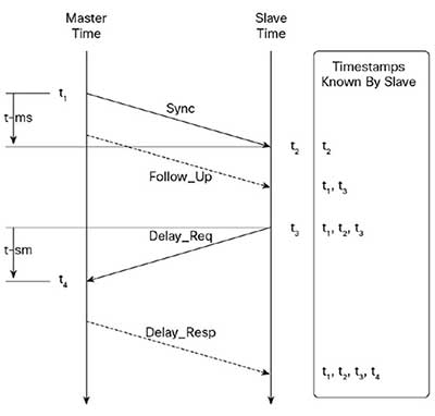
  1. The master clock sends the Sync message. The time that the Sync message leaves the master is time stamped as t1, which can be embedded in the Sync message itself (one-step operation) or sent in the Follow_Up message (two-step operation).
  2. The slave receives the Sync message; t2 is the time that the slave receives the Sync message.
  3. The slave sends the Delay_Req message, which is time stamped as t3 when it leaves the slave and time stamped as t4 when the master receives it.
  4. The master responds with a Delay_Resp message that contains time-stamp t4.

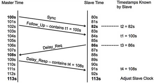
Example: the master time initially is 100 seconds and the slave time is 80 seconds. This is how time would be adjusted in the slave.

All PTP participants need to be PTP capable; this includes Ethernet switches but not the data sink (that is, the PC running DAQ software). The Clock in a DAQ module is named an Ordinary Clock. A Clock in an Ethernet Switch is named a Boundary Clock. The Master is selected automatically if no Grandmaster Clock delivers absolute time information. This mechanism is called Best Master Clock Algorithm (BMC).

Some DAQ topologies are line- or ring-structured with many switches, and thus Boundary Clocks use their own time control loops. As an alternative, the so called Transparent Clock (TC) allows an End-to-End (E2E) sync control and follow-up messages. The introduction of TCs allows for a far simpler solution to correct for variable switch latency. The basic idea of the TC is to measure the time a PTP event message has spent in the switch (the so-called residence time). The residence time is reported to the receiver by the message itself or by a subsequent Follow_up or Delay_Resp message. For this purpose a new message field has been added, the so-called Correction Field is a type of Time Interval that can be used to accumulate residence time along the path of the message, and may also be used for other kind of corrections. The key benefits are:

  • No configuration required: Transparent clocks do not have to calculate and do not have to be considered in the calculation of the BMC algorithm, so they do not necessarily have to send or receive management messages.
  • Quick reconfiguration of the network in case of faults.
  • Faster setup times: in initialization phase and after change in topology, transparent clocks do not have to re-synchronize to a master clock before they can be considered part of a valid synchronized path.
  • Perfect for small configurations.

Transparent Clocks using Peer-to-Peer (P2P) scale well with the number of devices attached to the subnet and can recover rapidly to changes in network topology. So this mechanism offers a high scalability and it’s best suited for deeply cascaded topologies (large scale systems using many switches in daisy chain).

What are the advantages of PTPv2?

  • It allows time synchronization between different device types from different vendors by a standardized protocol
  • It allows large distances between DAQ modules
  • It allows synchronization of different HBM product lines with each other. QuantumX, SomatXR and Genesis High Speed offers PTPv2 and enable data acquisition in all kind of situations including:
    • Distributed, mobile, outdoor in harsh environment
    • lab or field testing with many hundred channels or up to some mega samples per second and channel
  • High time accuracy in the sub-microsecond range between all participants when working with high data rates
  • Using Ethernet as standard
    • Electrical: up to 100 m standard Ethernet cable
    • Optical: large distance (some miles) between modules and galvanic isolation
    • No need for extra sync lines
  • Simple, administration free setup
    • automatic master selection
    • robust against master failures (smart slaves)
    • robust against topology changes
    • continuous time scale (no “jumping” time stamps, no roll over)
  • Absolute timing if necessary
    • A Grandmaster Clock based on GPS can be integrated and serve as absolute time when one or several DAQ systems are not working in the same network but its data needs to be analysed in a quick.

What are some typical Test & Measurement applications using PTP Time Sync?

Here is a list of some typical applications that highlight the benefits of PTP:

  • Widely distributed data acquisition modules used for:
    • Mobile testing of large scale ground vehicles (trains, construction): brakes, dynamics, structure, and more
    • Lab testing of aircrafts: mechanical (iron bird), structural (durability)
    • Monitoring of large structures: bridges, towers or wind energy plants using GPS based absolute time
  • Hybrid data acquisition systems used for:
    • Electric or hybrid vehicle dyno test combining the high-speed data acquisition system Genesis High Speed acquiring voltage and current with 2 MS/s per channel with mid-speed QuantumX acquiring mechanical and thermal sensor data
    • Lab testing of aircrafts: electrical (copper bird)
    • Lab testing of machinery or generator: electrical, mechanical and thermal
    • Mobile vehicle testing or monitoring using cameras, wheel force transducers or other supplements to analog or digital vehicle bus data
    • In general combining different DAQ systems from different vendors for any purpose
  • Mixed system architecture combining classic analog data acquisition systems with cameras or other information sources.


What are the procedures for Parameterization of PTP in the DAQ Software?

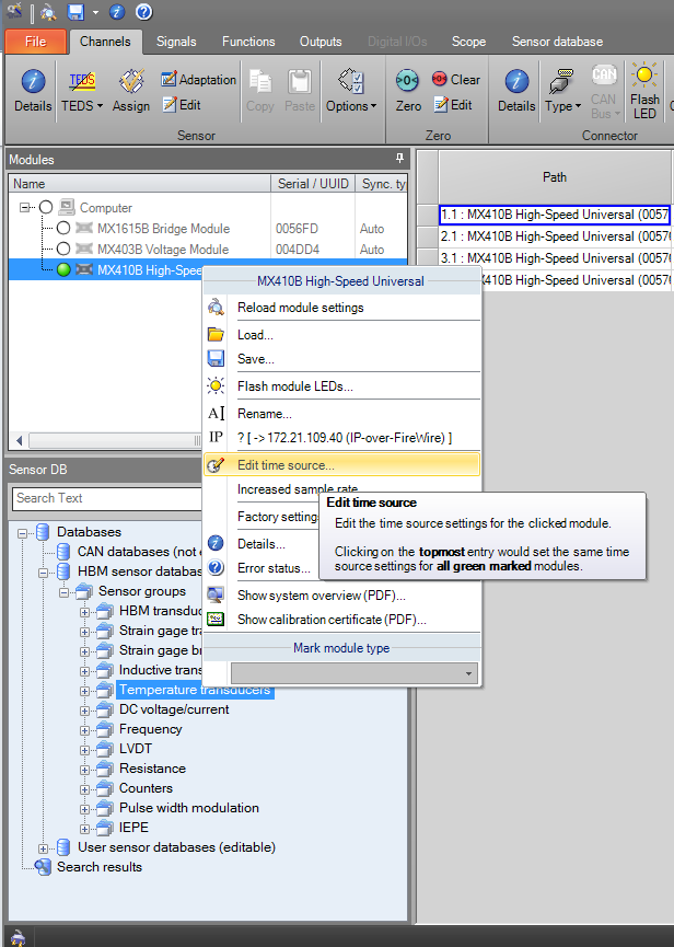
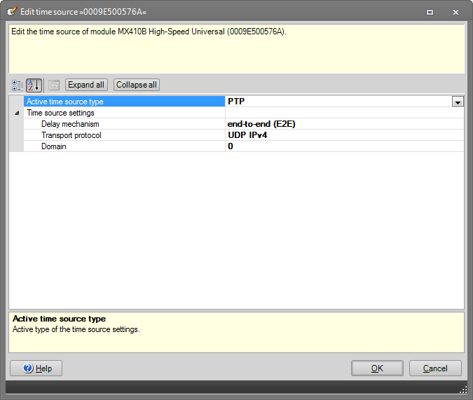
As QuantumX supports different time sync mechanism, parameterization is needed the first time you set up the network. The default or AUTO system clock timing mechanism is FireWire. In addition to that you can select the following timing sources or mechanism:

  • PTPv2
  • NTP
  • IRIG-B
  • EtherCAT

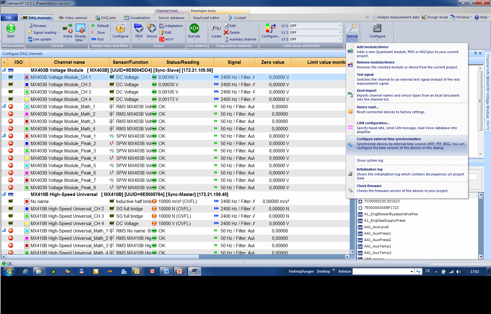
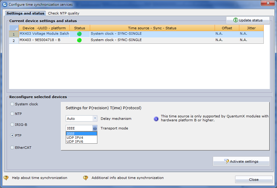
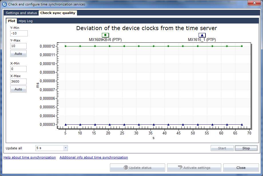
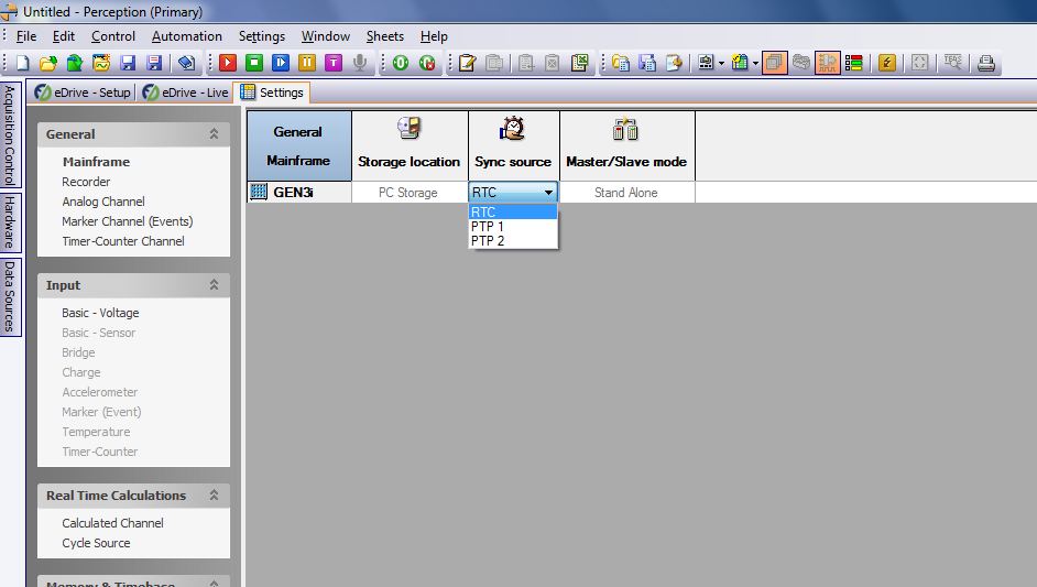
 You can use the software catmanEasy, MX Assistant or perception parameterizing PTPv2. Click on the screenshots to enlarge.

What are some recommended Ethernet PTP Switches and Grandmaster Clocks?

The following basic characteristics are necessary in selecting a PTPv2 switch:

  • Support of IEEE1588:2008 (PTPv2)
  • Transparent Clock (TC)
  • Delay mechanism: End-To-End  (E2E) or Peer-To-Peer (P2P)
  • Transport mechanism : IPv4 or IPv6

Recommended Switches

  • HBM: Gigabit Ethernet Switch EX23-R with the following parameters:
    • System design: ruggedized variant for outdoor use with 10 ports, 10-30 V DC supply, IP65/IP67, shock proof
    • Delay mechanism: E2E
    • Transport mechanism: IPv4, IPv6.
  • Siemens:  Scalance XR324-12M
    • System design: rack-size variant with up to 16 ports (electrical or optical)
    • Delay Mechanism:  E2E
    • Transport Mechanism:  IPv4/UDP
    • Mode: Transparent Clock
  • Hirschmann: RSP Ethernet switch
    • System design: DIN rail mounted with 11 ports in total
    • Delay Mechanism: E2E
  • Oregano Systems:  syn1588® Gbit Ethernet switch
    • System design: Desktop variant with 8 ports
    •  Delay Mechanism: 1-step with E2E
    • Transport Mechanism  :  IP4 (IPv6 has not been tested)
    • Mode: Transparent Clock (no parameterization)
  • B&K: PTPv2 Switch in the LAN-XI series
    • System design: Desktop with 8 ports electrical and 2 optical

Other switches, available in the market but not yet tested:

  • CISCO: IE 3000 Switch
  • MOXA: PT-7728-PTP Rack Type Switch
  • MOXA: EDS-405A-PTP Series

Recommended Ethernet Grandmaster Clocks

Integrating a grandmaster clock in the network is not a must as PTP offers a “best clock” mechanism, but in some applications absolute clock information is necessary.

  • Meinberg: LANTIME M600 - IEEE 1588-2008 Grandmaster Clock (GPS based)
    • System design: rack mounted solution, 110 – 230 V AC supply
    • Ports: 6 in total (RJ45)
  • Omicron: OTMC 100 (integrated GPS)
    • System design: small, for outdoor installations (IP67, 24 V DC supply, -40°C … +70°C / -40°F ... +158°F)
    • Ports: 1 in total, support of Power over Ethernet (PoE) according to IEEE 802.3af with < 2 W.
  • Your PC can be used as Grandmaster Clock as well 
    • We then recommend using a network adapter with Intel i210 chip. 

Is PTPv2 downwards compatible to PTPv1?

PTP Version 1 primarily targeted at test and measurement and industrial automation. It is a multicast protocol for use on a LAN with performance exceeding the capability of NTP.

PTP Version 2 or IEEE-1588-2008 is an enhancement to version 1. The versions are incompatible. Some of the many features of the newer PTPv2 standard include:

  • Multicast messages
  • Two-step clock
  • Peer-to-peer (P2P) or end-to-end (E2E) delay mechanism
  • Sync Interval: 1, 2, 4, 8, 16, 32, 64 or 128 packets/second
  • Delay Request Interval: 1, 2, 4, 8 or 16 seconds
  • Support the Transport protocols: IPv4 and the modern IPv6

What accuracy do I get when using PTPv2?

Time accuracy heavily depends on the type of network and its devices. We recommend setting up a private LAN where all network participants fully support PTPv2. With this configuration time accuracy can go down to 100 nanoseconds device to device and its channels. Still you need to consider that different data rates and filters can introduce timing jitter and phase delays.

What is the difference between hardware and software time stamping?

The main difference is in the synchronization accuracy that is achievable. With software-based time stamping used for example in NTP, you can see slave synchronization accuracies down to 100 microseconds in small networks but typically 1 ms. With hardware time stamping it is possible to achieve time synchronization accuracy down to 100 nanoseconds. However, in order to get this level of accuracy, the network topology such as switches and slave hardware must support hardware time stamping.

Can I also use a standard switch and if so what is the effect?

Using Non PTP capable switches is risky. Transferring PTP messages then depends on traffic and thus it is critical in the overall timing. In case the switch supports QoS, this can be solved by a rule to increase priority of PTP packages. In general we do not recommend using Switches without PTPv2 support. In the worst case, PTP packets can be lost and timing and thus required data would no longer be reliable.