CEDEX: Test Track - Accelerated pavement testing CEDEX: Test Track - Accelerated pavement testing | HBM

The CEDEX Test Track - Accelerated pavement testing

The Transport Research Center of CEDEX in Spain conditioned, monitored and measured data from more than 240 channels distributed strategically around the track by HBM’s data acquisition (DAQ) System, the proven MGCplus DAQ system.

What is accelerated pavement testing?

Accelerated Pavement Testing can be defined as the “controlled application of wheel loading to pavement structures for the purpose of simulating the effects of long-term in-service loading conditions in a compressed time period”.

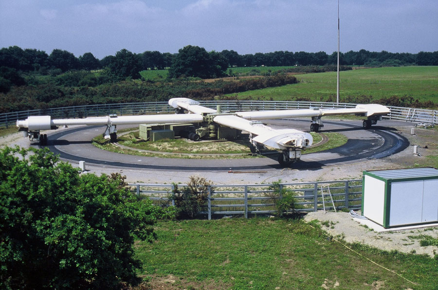
There are twelve full-scale facilities operating in Europe and a similar number in the United States of America, besides other facilities in Mexico, Brazil, South Africa, Australia, New Zeeland, China and Japan. It can be stated that nowadays the Accelerated Pavement Testing constitutes a basic pillar of road research worldwide. There are two kinds of test facilities: circular and linear shaped. Figure 1 Figure 2

About CEDEX

The Civil Works Study and Experimentation Centre, more commonly known by its abbreviation in Spanish, CEDEX, is a public body that applies cutting edge ideas and technology to civil engineering, construction and the environment. The technological support provided by its facilities and laboratories is defined in specific agreements. The CEDEX also plays an important role in technology transfer as part of its aim to disseminate the knowledge obtained.

The Test Track

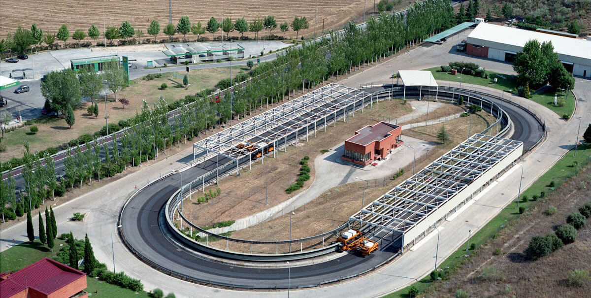
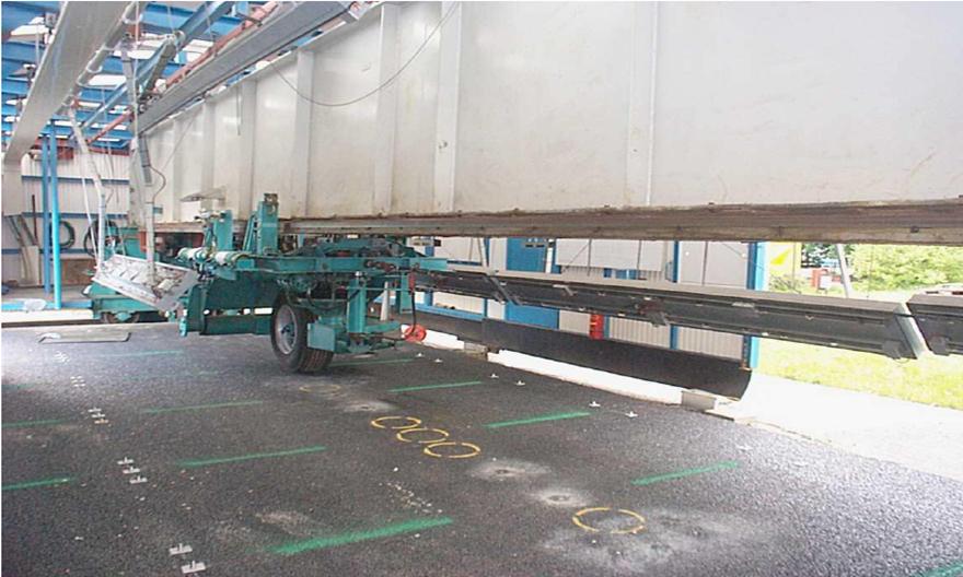
The CEDEX Test Track is in between, having two straight sections of 75m each, joined by two additional curved sections with a radius of 25 m. A rail beam located on the inside perimeter of the track serves as a guide for two automatic vehicles. Figure 3

Considering that the six sections of pavements under test are installed on the straight segments of the track, this facility could be classified from the test point of view inside the second group of linear-shaped facilities. The total length travelled by the load test wheel is of 304 meters by cycle. The curved segments are not used for test purposes and are assigned to other studies like surface materials, surface treatments, paints, wearing paths, etc.

The testing of the pavement sections is carried out in the straight stretches, and therefore the results are comparable to those obtained in other linear test tracks. Six 20-25 m long complete pavement sections can be tested simultaneously.

Meanwhile the curved segments are based on the terrain, the straight segments are installed inside two watertight U-shaped test pits made out of reinforced concrete. The concrete test pit, 2.6 m deep and 8 m wide, enable the building of embankments of at least 1.25 m in height as well as the use of conventional machinery and the usual road-building procedures. The purpose of using concrete test pits is to isolate the performance of the pavements from that of the surrounding ground, allowing homogeneous support to the pavements throughout each test and between different tests in such a way that the results are comparable. It also allows the subgrade to be flooded for testing under different groundwater conditions.

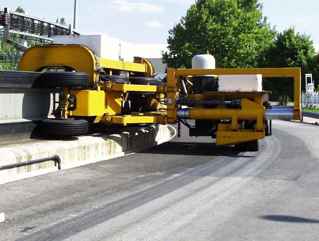
The two test vehicles apply the load by gravity through a half heavy axle. The load can be fixed in between 5.5 and 7.5 Tons and is fixed at 6.5 Tons, equivalent to the maximum allowed load in Spain for a single axis (13 Tons). The suspension system is pneumatic. The test wheel is equipped with two twin wheels or one single balloon-shaped wheel at 8.5 Kg/cm2 inflating pressure. Both the suspension system so as the traction test wheel are conventional ones used in Roads’ Transport. The circulating speed is of 40 Km/h, with a maximum allowable speed of 60 Km/h. Figure 4

Thanks to a hydraulic actuator, the test wheel can be positioned in seven different transversal paths, producing in this way a footprint band of 1.0 to 1.3 m width. The automatic control of this position allows reproducing a real statistical distribution of passages according to real traffic.

This test facility is fully controlled from a centralized Control Center, situated in the geometrical center of the test track. The control program has been specifically developed for this application. In this way the whole facility can work unattended once programmed. The test frequency is higher than 1x10⁶ cycles by year.

Measuring parameters

When a wheel moves along a road, stresses and strains develop at any point of the pavement structure; this stresses and strains depend on the type, magnitude and direction of the load, pavement structure, type of subgrade, temperature, depth, etc.

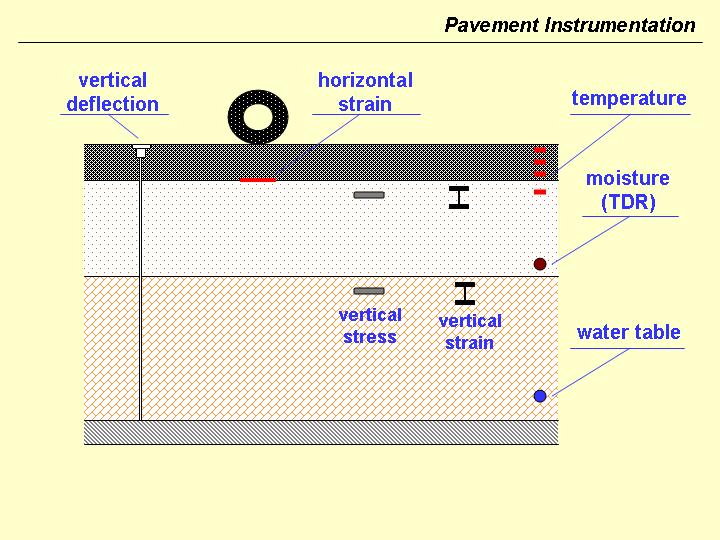
The instrumentation of the pavement makes possible the measurement of the stresses and the strains that appear in different parts of the pavement under the pass of a load, and especially those that are considered to be critical.

For each layer, the critical points as well as the tensodeformational variables are different, and that has to be considered when choosing the type of sensor and its placement.

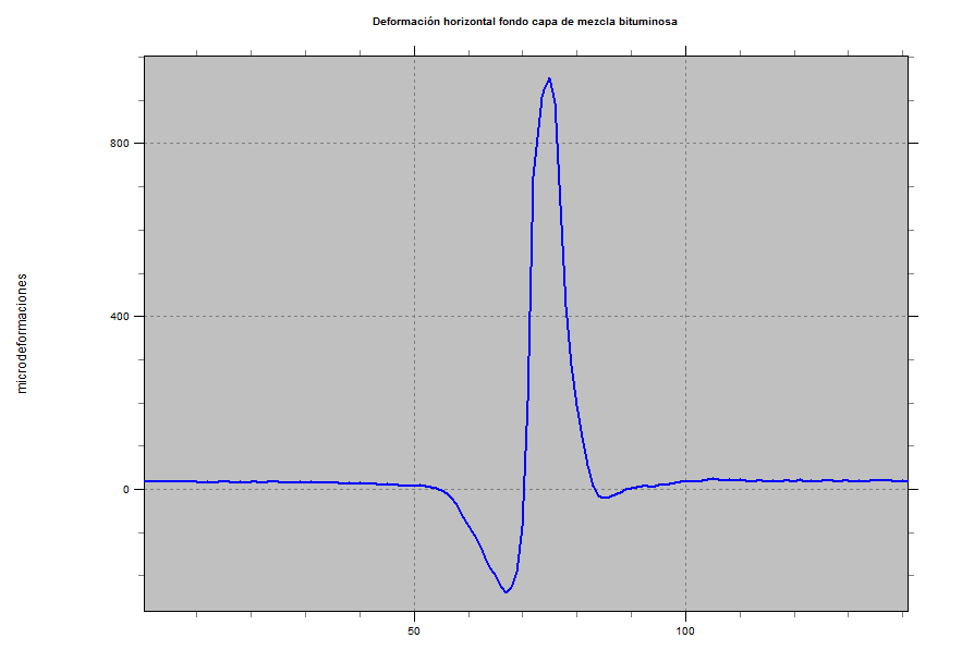
Horizontal tensile strain at the bottom of the bituminous layer is considered the most important response variable for flexible pavements. Consequently, the instrumentation of the asphalt mixture layers is mainly focused on measuring horizontal strain at the bottom of the layer.

Granular layers and soils fail mainly due to accumulation of vertical strains. Therefore, the instrumentation of the soils is especially focused on measuring vertical stresses and strains.

Pavement deflection sensors are also placed in order to measure the transient response under the pass of the moving wheel. These sensors are placed on the top of the asphalt layer and anchored to the bottom of the test pit.

Finally, a series of sensors are installed in order to collect data from environmental and load related variables: temperature, moisture and water table, speed, transverse position, etc. Figure 5
Description of the control system of the facility

The automation process was mainly considered during the design phase of the facility with the aim of reaching a test life cycle in a continuous operating mode with minimum interruptions. Moreover it is important to point out that the facility, especially the vehicles and their control system, are prototypes designed, built and commissioned specifically for the Spain test track and they have been completely developed with European Technology. Figure 6

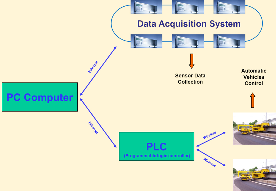
The Control System of the CEDEX Test Track is composed of two fundamental parts: the PLC System and the data acquisition System. Those are related to each other and both are managed by a single one (Control Computer) connected to them using an Ethernet network. The first one (PLC System) is in charge of managing the vehicles by means of the control of parameters like speed, transverse position, air pressure of the spare tires, etc., and all the necessary variables for the vehicle maintenance and facility security, adding: electrical consumption, position detectors, etc. The other system (data acquisition System) is in charge of the pavement instrumentation measurement process.

The PLC System is formed by one PLC Master that is located in the Control Center and two PLC Slaves that are located inside each vehicle. The PLC Master establishes a connection through a wireless Ethernet network to govern the PLC Slaves of the vehicles.  

Data from more than 240 channels, comprising strain gauges, LVDT’s and Pt100, distributed strategically around the track are conditioned, monitored and measured by HBM’s data acquisition (DAQ) System, the proven MGCplus DAQ system. This DAQ system, in use by many structural test programs around the world, as well as in Civil Engineering Monitoring, is designed to provide high quality measurement data which can also significantly reduce the cost and burden of cabling.

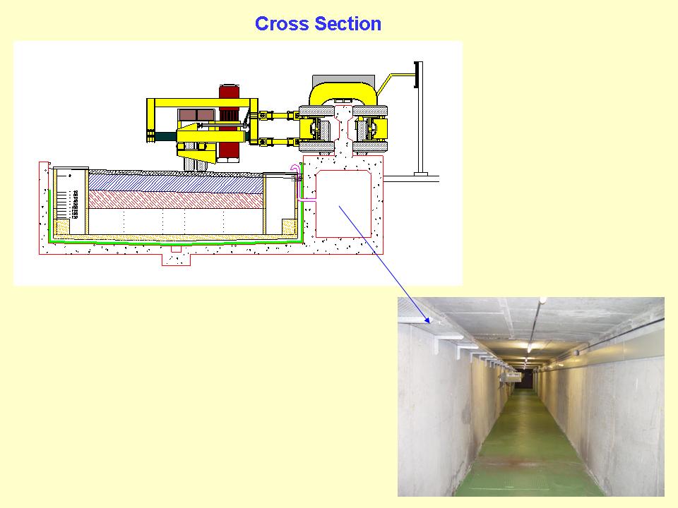
In the test track, a gallery is available on the straight stretches next to the test sections where the power supply and data acquisition devices are located, as well as the keystone jacks for plugging the MGCplus devices. It was thus designed to achieve the minimum distance possible between the sensor and the conditioning device to avoid distortion of the output signal and to convert the analog signal to a digital signal. Figure 7

Instrumentation management tasks

The system for data acquisition of the sensors, which is fully automated, has been designed and developed by CEDEX and makes real-time measurement and storage in database possible for up to 240 sensors on every measurement test.

        The management tasks are divided into three processes: 

  • Management sensor process.
  • Measurement process.
  • Data storage and analysis.

Management sensor process

Once the plan of instrumentation for each test has been designed and the supply of each sensor has been carried out, the next step is to register it into the system database of the Control Computer. It is then time to include all the data which define the sensor, its location, the optical measurement startup sensor, relevant dates and state of activity.

After the sensor has been registered in the database, the next step is setting the MGCplus modules to carry out the calibration curve of each sensor, including whole measurement chain (wires and device), relating the electrical measure to the physical measure. Then the recording parameters (sample rates, time, sensors activated, and trigger) are set with the PC card manager of the MGCplus and the .MPR file is saved. It is usually programed two different sampling rates; one of them is for recording the static variables and the other one for recording the dynamic variables. Figure 8

There are also additional tasks which simplify the instrumentation maintenance work and feature graphical and numerical real-time monitoring functions of the readings.

Measurement process

Within the data acquisition System, there are two distinct types of tests:

  • Dynamic tests
  • Special tests

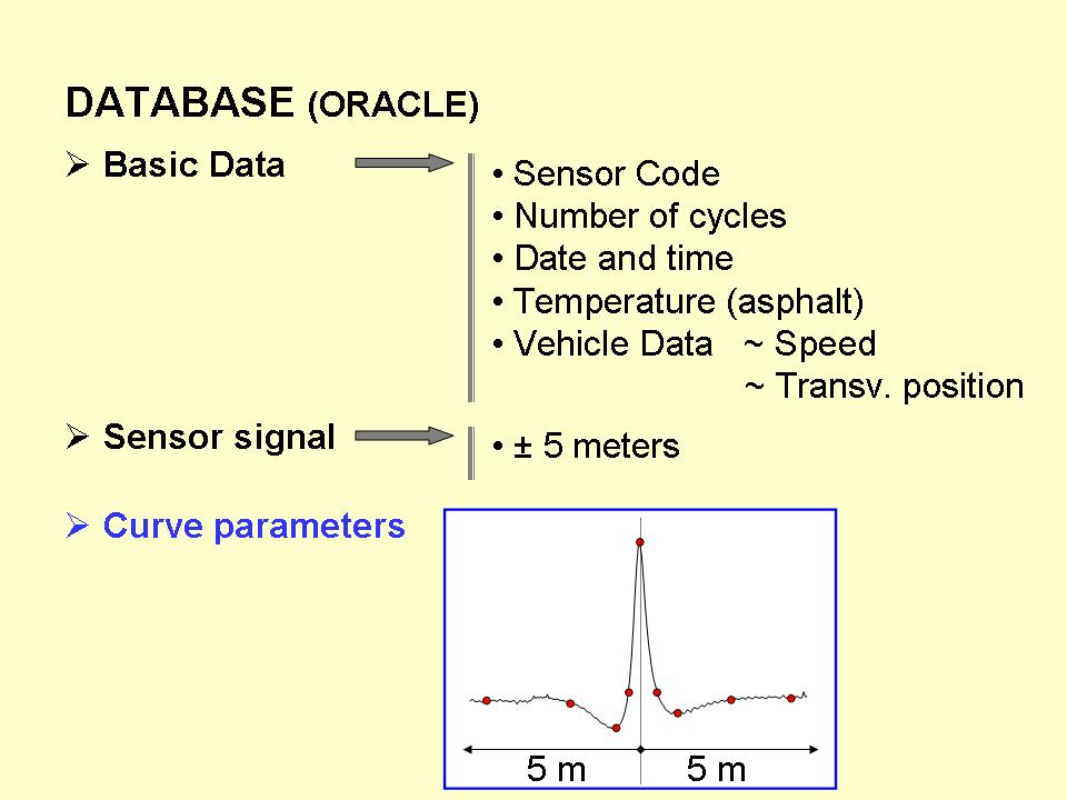
The dynamic test refers to the systematic measures taken with the instrumentation while the vehicle is in motion. When carrying out this kind of tests, the sensors being measured have to be previously defined, up to a number of 240 per test. Besides, a results file (ASCII) is created to include all the variables required for the analysis of curves, such as pavement temperature, environmental temperature, number of cycles, transverse position, vehicle speed, date and time.

Dynamic tests are activated automatically. They can be activated by means of three different events, which are selected when the test is being scheduled. These three events are the following:

  • Number of cycles. The test begins when the vehicles cover a predetermined number of cycles.
  • Time. The date and time of the beginning of the measurement are indicated.
  • Temperature. It begins when the pavement temperature (defined by the user) reaches a certain value.

The presence of staff at the facility is not required for this kind of tests, which are performed 24/7.

When the event that triggers a test takes place, the Control Computer instructs the PLC Master to position the vehicles on the conditions required for the test (speed and transverse position). Once the vehicles are placed in the right position for the scheduled test, the Control Computer sends a set of low level commands to each MGCplus connected to the Ethernet network. These commands transfer .MPR files with the recording parameters to the device and activate them to be prepared for the acquisition process. There is one optical sensor connected to each MGCplus to use for triggering the measurement. When the vehicle selected pass by the optical sensor which activates the beginning of the data collection, and is stopped after a period of time, defined in the recording file.  Figure 9

When the vehicles complete one cycle from the beginning of the data collection, the Control Computer connects to the MGCplus devices to transfer the data collection file that has been created from the DAQ to the Control Computer and convert it into ASCII format by means of the Catman control ActiveX. All of that has been programmed inside a Visual Basic script which also realizes a signal processing to change time to distance, cut and resample in order to store the number of samples that are interesting for analysis.

After that the Control Computer has to put all the data together in the results file (ASCII), the data from the PLC System regarding the vehicles (speed, transverse position) and the data from the data acquisition System regarding the sensor measurement process.

Once every piece of data is stored, the test finishes and the PLC System in charge of the steering of the vehicles regains control. This test can be scheduled cyclically depending on the number of cycles, after a determined period of time or when the desired temperature values occur.

The special test refers to other kind of measures that would be carried out with the instrumentation without using the whole Control System, directly with the MGCplus devices.

We would like to highlight the following three types of tests as special tests:

  • Temperature traces. There are two Siemens ET 200 as part of the PLC System in which have been connected the analog outputs of the MGCplus to have a continuous pavement and environmental temperature registered. These are used to analyze not only the instrumentation but also the damages of the pavement.
  • Manual Start. These tests can be performed not only with vehicles in motion but also with vehicles stopped. They begin when a trigger is sent. This kind of test is used to study in detail some specific variables when the vehicle is passing by and, unlike the dynamic tests; they are made with a sample frequency up to 3000 samples per second. This test is also used to measure the response of one or various sensors to equipment other than the test vehicles, e.g. FWD devices.
  • Start by optical sensor. It has the same features as the Manual Start test, but, in this case, the measurement is triggered by one of the optical sensors on the test track.