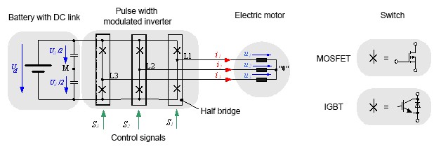
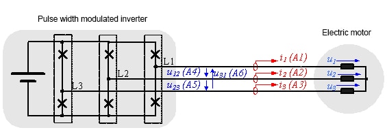
A pulse width modulated inverter converts a DC voltage into an AC voltage with variable frequency and amplitude. Due to its simplicity, the two- level inverter is frequently used. Fig. 1.1 shows the circuit diagram of a three--leg, two-point inverter. Each leg of the pulse width modulated inverter consists of a half-bridge with two IGBTs and the corresponding power diodes. MOSFETs can also be used for lower battery voltages. No additional diodes are required for pulse width modulated inverters with MOSFET, as they are reverse-conducting.
A half bridge connects a connection point in the machine (depending on the switching state of the transistors) with the positive or negative pole of the DC link. In the ideal inverter initially considered here, the switches and diodes should not have any conducting losses in the activated state (u = 0), and in the deactivated state, should ideally be disabled (i = 0). The switching state should also involve no time delay.
The working method of a two-point inverter is especially clear when the time curve of the output voltage of a half bridge is considered against a "virtual" medium voltage tap M in the DC link. The inverter voltages eνM with ν = 1, 2, 3, according to the corresponding control signal, can take on the value +Ud /2 with Sν = 1 or the voltage value -Ud /2with Sν = 0.
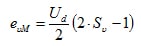
(2.01)
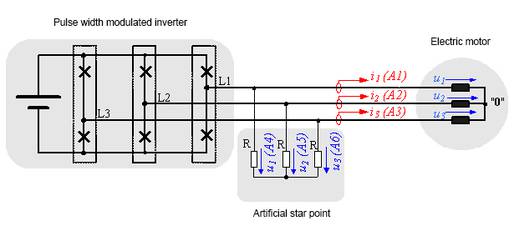
To calculate the line voltages in the machine, first the mesh equations are set up:
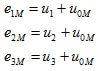
(2.02)
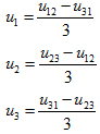
If the correlation u1 + u2 + u3 = 0 is taken into consideration, the zero system of the inverter voltages can be calculated:
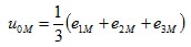 (2.03)
A three-phase inverter has three legs and two switches per leg, resulting in only 2³ =8 different voltage states. This limited number of voltage states has created the need for advanced control in inverters in order to supply variable frequency and voltage amplitude to motors. Pulse width modulation is a switching control strategy that allows for a spectrum of voltage amplitudes and frequencies to be achieved with the 8 switching states. It does this by supplying DC pulses of different lengths to the motor, which are effectively a sine wave when switched at a high enough frequency.
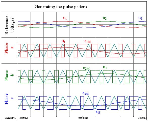
Fig 2.1 shows how the control signals are generated with simple sine-triangle modulation. A triangular-shaped voltage is compared with the desired sine voltage. If the sine voltage is greater than the delta voltage, a positive voltage is generated. The pulse width modulated inverter switches to a negative voltage if the sinusoidal voltage is less than the delta voltage. The frequency of the triangular voltage is equivalent to the switching frequency at which the power semiconductors switch.