RDS: Strain Gauges For Determining Crack Propagation
The RDS strain gauges are used to determine crack propagation in a component. HBM offers four different types:
The RDS strain gauges are used to determine crack propagation in a component. HBM offers four different types:
This change in resistance can be measured using a resistance meter or strain gauge amplifier.
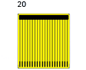

A resistance measurement can be used to detect the signal of the RDS crack propagation gauges. HBM DAQ systems can be used for this application (e.g. QuantumX or MGCplus).
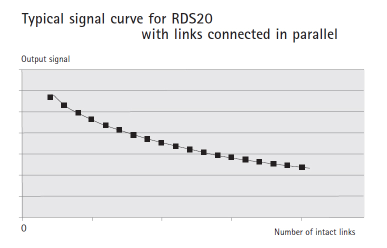
The resulting resistance (R) of the RDS is dependent on the number of torn links and can easily be calculated. In this case, n identical resistors (Ri) are connected in parallel:
![]()
If a grid line is interrupted, this is described by
![]()
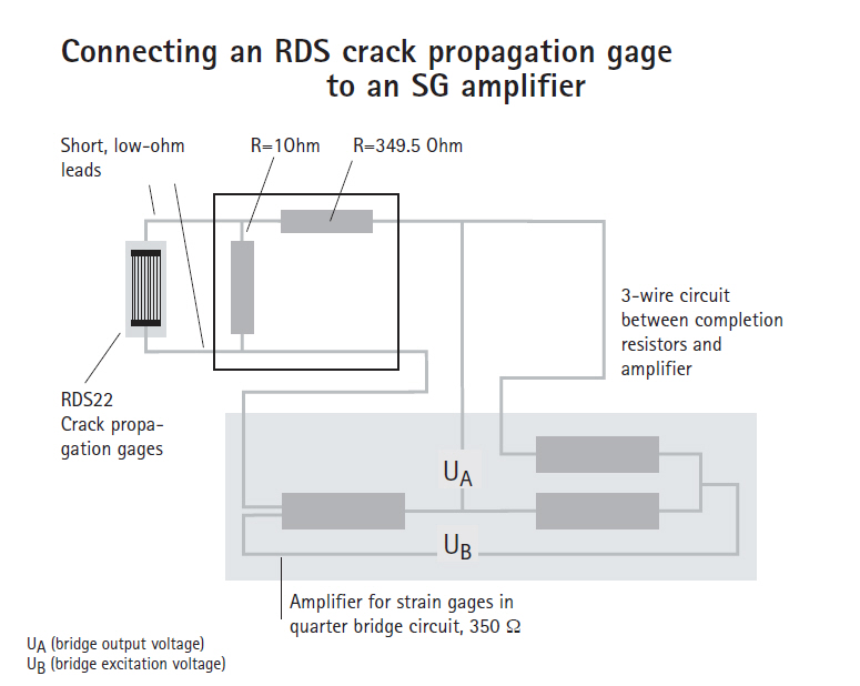
However, the measurement can be performed just as well with a measuring amplifier for SG measurements. The circuit diagram sketch shows how the RDS has to be complemented to obtain a resistance change that is inside the measuring range of an amplifier for strain gauge quarter bridges.
To minimize the effects of temperature, temperature-stable fixed resistors or SGs should be used as completion resistors. Greater sensitivity can be obtained by selecting a parallel resistor with a higher resistance value.
Do you have special requirements that are not adequately covered by any of the strain gauges in our standard program? Are you looking for an equivalent strain gauge for the product you are currently using? Have you designed your own strain gauge? Contact us, and we will produce customized strain gauges for you.
|
|
|
Dimensions [mm/inch] |
|
| ||||||||
Ordering | Nominal | Link | Measuring | Carrier
| Pitch t | Number | Maximum Excitation Voltage | ||||||
Ω | a | b | c | d | |||||||||
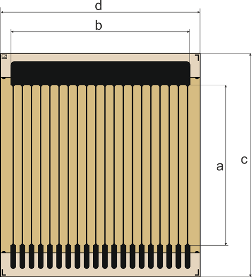 | 13 | 20 | 22.5 | 28 | 25 | 1.15 | 20 | 1.5 | |||||
| 44 | 22 | 5 | 27.8 | 6.8 | 0.1 | 50 | 0.8 | |||||
| 28 | 40 | 8.4 | 47 | 10 | 0.85 | 10 | 2.5 | |||||
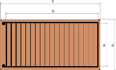 | 3.5 | 17.8 | 38.75 | 21 | 41.6 | 2 | 20 | ||||||
| 제목 / 설명 | 언어 | 제품 | 언어 | 종류 |
|---|---|---|---|---|
| 데이터 시트 | ||||
| Dehnungsmessstreifen - Katalog | German | |||
| Strain Gauges - Catalogue | English | |||
| Тензорезисторы - катало́г | Russian | |||
| Declaration of Conformity | ||||
| Strain Gauges and Accessories - Statement of Compliance | English | |||