TEDS: cost savings, short setup times & application safety TEDS: cost savings, short setup times & application safety | HBM

TEDS for cost savings, short setup times and application safety

When it comes to finding the right sensor, technical requirements are not the only thing that count. Simple handling is at least just as important. Installation should be quick and easy, and the parameterization of the measuring chain should be efficient and error-free. Insight into modern solutions using force sensors as an example.

Traditional force sensors have a lot to offer in mechanical terms, but the calibration of the measuring chain in line with the relevant sensor properties is a considerable task. Responsible members of staff must be just as well acquainted with sensor technology as they are with the operation of amplifiers. No wonder a lot of measurement engineers want a sensor that contains its own calibration data, serial number and type name. TEDS ("Transducer Electronic Data Sheet") technology has been providing the solution for several years.

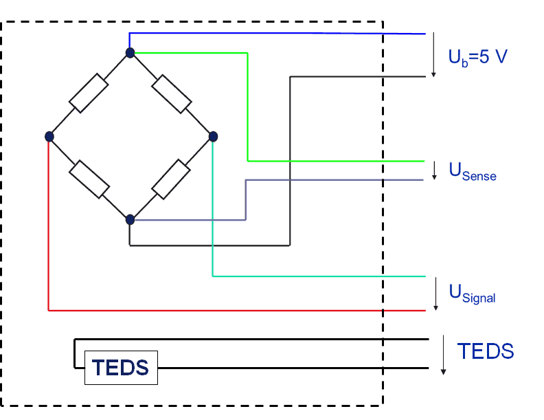
TEDS: What is it exactly?

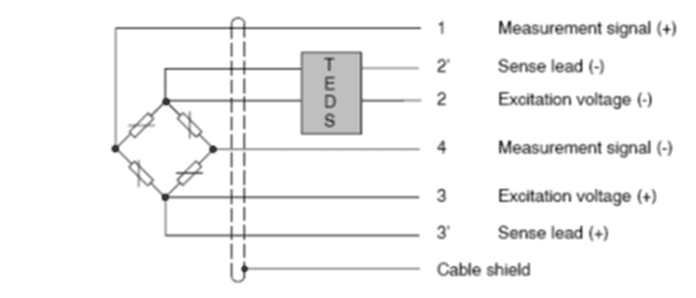
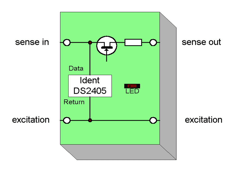
A TEDS chip carries the sensor's unique information like a fingerprint. This significantly simplifies the handling of sensors. The international standard for TEDS is IEEE1451.4. This standard describes the circuit connection of TEDS. Standardization offers users the advantage that sensors and amplifier technologies from various manufacturers can be combined in one system.

Many devices can read and describe TEDS

TEDS has become widely used at HBM. Almost all sensors are optionally equipped with TEDS (either as a standard option or custom solution). HBM amplifiers can read TEDS, many devices have the option to describe TEDS.

All data is stored in so-called templates in a TEDS chip. These templates can be imagined as tables, where the sensor parameters are listed.

Each TEDS chip contains a template called Basis TEDS. The following information is stored in this template:

  • Manufacturer of the sensor
  • Type series of the sensor
  • Version letter
  • Version number
  • Serial number of the sensor
               

The TEDS procedure stores the required data encoded in templates on the chip.

Coding example

If number 31 is stored under the Manufacturer ID in TEDS, this means the manufacturer is HBM. The chip in the sensor will now transmit "31" to the amplifier. It is therefore clear that the firmware in the amplifier system must know the code. The same applies for information about the sensor type series. The relevant sensor manufacturer has these data sets ready, provided the standard is supported. At HBM, this information is available for download from the homepage.

Templates for practically every sensor technology

Other available templates can parameterize the acquisition system with a relevant sensor description.

The parameters for the sensor data are transferred once the basis TEDS has been read. Strain gauge-based force sensors are so-called bridge sensors, i.e. a sensor that works in accordance with the Wheatstone bridge circuit. IEEE1451.4 defines a relevant template.

In addition to information about the sensitivity of the force sensor (i.e. the combination of rated output and rated force), the basis TEDS also contains other important data like the reference excitation voltage, bridge resistance or the calibration date (if any). Other strain gauge sensors, e.g. for pressure metering, are handled similarly, provided they are also Wheatstone bridge circuits.

It is important to note that these entries can be overwritten with any new calibration. Should there be slight changes to the rated output of the sensor, and this change is noted during a recalibration, then the new rated output value can be written to the TEDS after calibration.

The HBM calibration laboratory or the user can optionally write the TEDS data if an on-site calibration is needed.

In addition to bridge sensors, TEDS technology supports virtually all types of sensor technology such as frequency outputs (incremental encoders, torque sensors) or voltage outputs using relevant templates. Other templates are available for linearizations or the calibration of display units at an output interface, regardless of whether it is a visual display or bus system, such as EtherCAT or PROFIBUS.

Small amounts of data – fast transmission

The data volume to be transferred is minute - which is a great advantage when it comes to the transmission speed.

The user can optionally describe the entire TEDS if sensors are used for which the manufacturers do not support the standard. TEDS chips are available from HBM in case an application is to utilize sensors from a manufacturer that does not offer TEDS. These can then be installed in the relevant sensor or its cable, and can then be described using the relevant hardware. In effect, any existing sensors can be set up ready for plug-and-play.

Connecting the TEDS module

Class 2 connection

IEEE 1451.4 allows a variety of connection options for TEDS modules. The easiest method by far is to use two additional cables to connect the TEDS module. The illustration shows this type of connection.

This method is an option, but often has limits in terms of implementability:

  • The cabling for sensors in assembly lines and test benches is often done via six-core cables (two strands for power supply, two sense lines for the measurement of cable influences, and two for the transmission of the measurement signal). Adding two more cables would be equivalent to renewing the cabling entirely - generally a no-go criterion.
  • High quality measuring cables for strain gauge sensors are not available in eight-core versions for all application conditions.

Zero wire connection

That is why so-called class 1 sensors are defined as standard. Their sensor cables are either used to read the sensor data from TEDS or for measurements - switching is completed electronically. The drawbacks described above are avoided, although users cannot take measurements while the amplifier is reading sensor data. This drawback is generally accepted, as parameterization is completed quickly and it makes sense to only take measurements once the amplifier has been calibrated.

Class 1 connections are mostly used for IEPE transducers. To the best knowledge of this author, this method is not used in strain gauge measurement technology and will therefore not be discussed any further here.

Another method would be the so-called zero-wire configuration. This circuitry does not require additional cables, just like the class 1 sensors. HBM developed this method some years ago to comply with requirements of customers, who need to implement TEDS technology in their existing infrastructures.

In this method, the TEDS module is installed with a tiny connection between the voltage supply and sense line of the measuring bridge as shown in the illustration below.

This type of circuit also does not allow users to read sensor data during the measuring process. A voltage pulse toggles the module from parameterization to measurement. An electronic switch opens and interrupts the sense line; data can now be read. The switch then closes again and toggles back to measuring mode.

The IEEE1451.4 standard is currently under revision. The zero wire technology will become part of the new version and will be available for use by any manufacturer license-free.

TEDS impact on measurement accuracy

The question of measurement accuracy remains, as the connection will require an additional resistor in the sense line. Essentially, the 6-wire configuration measures the voltage between the bridge excitation voltage line and sense line. The input resistance of the amplifier is very high, which means the small serial resistance is subsequently insignificant. Additionally, the sensors are calibrated via the TEDS chip, which means that any influences will be taken into consideration.

Intensive measurements have an effect on zero point of significantly below 50 ppm. The spread (difference between zero point and measurement signal at full strength) remains unchanged. A TEDS module therefore has no impact on the measurement accuracy of a bridge sensor.

Where is the TEDS installed?

As discussed above, TEDS must always be inseparably linked to the sensor. That is why the preferred installation location is inside the sensor.

This may not be possible in the case of very small sensors, e.g. force sensors with a mechanical design that does not allow the installation of the TEDS module in the spring element. In that case the TEDS chip can be installed in the plug. These sensors are only available with in-plug mounting of TEDS. HBM offers almost all sensors with zero wire technology, which offers the most advantages in conjunction with strain gauge sensors. Class-2-designs are used only if the TEDS must be mounted inside the plug, and the plug model does not allow for the inclusion of a zero-wire configuration.

Custom solutions are available for all other configurations. That may be a TEDS motherboard as an individual part or in cable-mounted solutions.

Outlook

As mentioned above, the IEEE1451.4 standard is currently being revised. The work group includes industry representatives and users, including HBM. Practical experience has shown that a predefinition of the display unit is an important requirement, which will be taken into consideration in future. It will also be easier to carry out linearity corrections. The zero wire technology will be added to the standard. Organization and circuitry will remain unchanged, which means that sensors that are currently delivered will remain perfectly usable in the future.