Using the new PME modules is not only more cost-effective but also gives the user a significant improvement over conventional analogue technology using IGMD. The assembly is simpler to fit on the standard rails in the control cabinet (Fig.3), minimal wiring is needed thanks to the plus-in screw terminals, an onsite display is provided in case a service visit is ever needed, and there is even a digital bus lin over CANopen and/or Profibus DP.
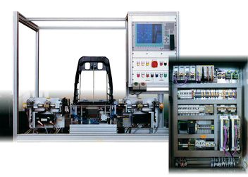
Fig.3. Controller for PME modules and servo power unit using a Siemens PLC and Profibus DP interface
Advantages of the PME system over the previous solution
- Digital signal conditioning, therefore 100% reproducible
- Integrated display and control panel for on-the-spot service
- Bus link over CANopen and Profibus DP for communication with PLC and PC
- Scalable analogue output (0 to ±10V or 0/4 to 20 mA selected by switch)
- Additional functions such as filtering, taring, limit values and digital I/Os (24 V PLC level) included as standard Industry-standard design – EMC compliant aluminium die-cast enclosure, electrically isolated 24 V supply
- Industry-standard design – EMC compliant aluminium die-cast enclosure, electrically isolated 24 V supply
The PME Setup Toolkit
It has also proven beneficial to use the PME Setup Toolkit for entering settings and parameters. This Setup Toolkit includes not only a Windows Setup Program but also an adapter for converting a parallel interface to CANopen and a cable for connecting the PC and module. Using this Toolkit provides an easy, quick and reliable way of assigning parameters to all PME modules. All the settings can then be saved to a diskette or hard disk and, in the event of a service requirement, the parameters can be downloaded to another module in the shortest possible time.
Although all relevant measurement data and all digital I/O signals can be transmitted over Profibus DP, subsequent data processing is still carried out in analogue mode in the case in question. The reasons for this can be found in the design adopted for the hardware and software of existing equipment and the special characteristics of the data analysis required. One measured value has to be imported per degree, so that the angular velocity amounts to 1°/ms. So far these requirements can only be fulfilled by using an IPC with a data entry card which is independent of the operating system. The graph shown here (Fig. 4) shows a typical analysis:
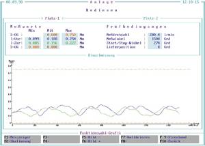
Fig.4: Typical plot showing torque and angle rotation
