Typical vs. New Testing Method
The Electrical Drive Train and Related Signals
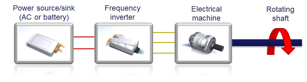
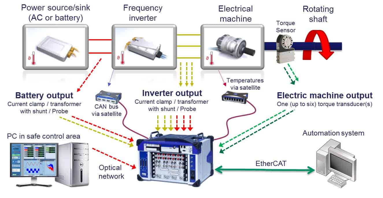
Electrical drives are used in a wide variety of applications, including electric vehicles, ship motors, high speed trains, airplane electric wheel drives and actuators, forklifts, motorized appliances and wind energy, basically every electrical machine that is inverter driven or contains a variable speed drive. The key is to design and test for the maximum efficiency at all operating points in the entire drive train safely, accurately and rapidly. This includes optimizing the inverter, the motor or electrical machine, the matching between the inverter and the motor and the drive strategy, as seen in Figure 1.
The better the inverter and motor are matched, the higher the efficiency. To improve inverter-motor matching, the motor needs to be carefully characterized with the inverter and sometimes the inverter may need improvements in the algorithm to drive the motor more efficiently. This can only be done by analyzing the raw data at all operating points along the drive train.
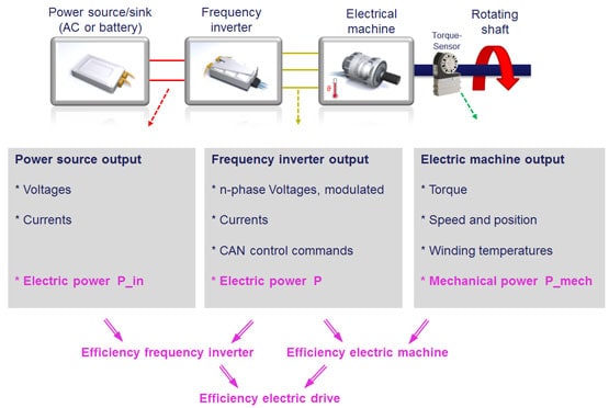
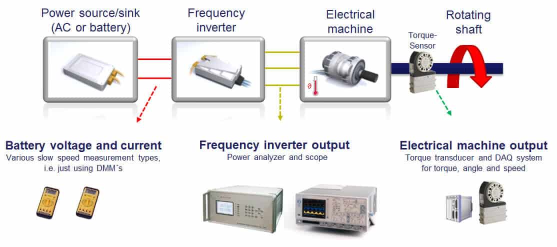
Electric drive trains contain many signals that need to be recorded in order to analyze and improve efficiency. Referring to Figure 2, signals include battery voltages up to 1000 Volts and currents up to a few hundred Amps. Inverters produce pulse width modulated voltages up to +/-1000 Volts, often in 3 phases, sometimes more and currents up to a few hundred Amps. A torque transducer can record a motor’s torque and speed, as well as its position for advanced analysis. Measuring each of these voltages and currents enables calculations of the electrical power from the batteries, the electrical power from the inverter and the mechanical power from the motor. Calculating the ratios produces the efficiency of the frequency inverter, motor and the entire electric drive.